
Subscribe to Our Youtube Channel
Related Manuals for Radiant R2KA 28/20


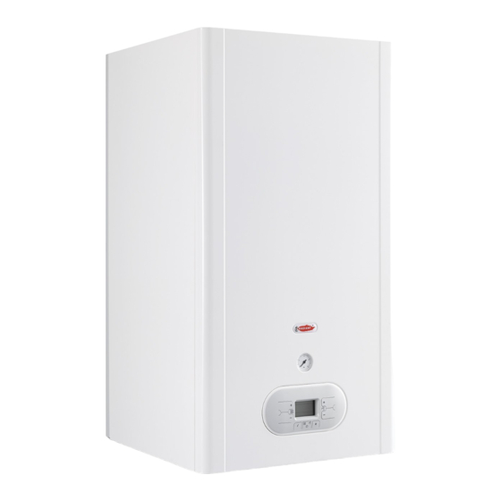
Summary of Contents for Radiant R2KA 28/20
- Page 1 Installation, Use and Maintenance Manual for model R2KA 28 /20 Condensing boiler with integrated heat exchanger for domestic hot water side and storage 0476 R2KA 28 /20 - RAD - ING - Manuale - 1806.1_SK.2...
-
Page 2: Table Of Contents
SUMMARY SUMMARY INTRODUCTION 1. INSTALLER SECTION 1.1. INSTALLATION 1.1.1. GENERAL INSTALLATION WARNINGS 1.1.2. BOILER LOCATION ENVIRONMENTAL REQUIREMENTS 1.1.3. REFERENCE LEGISLATION 1.1.4. UNPACKING 1.1.5. OVERALL DIMENSIONS 1.1.6. JIG 1.1.7. POSITIONING AND MINIMAL TECHNICAL SPACES 1.1.8. CIRCULATOR PREVALENCE/FLOW DIAGRAM 1.1.9. HYDRAULIC CONNECTION 1.1.10. - Page 3 SUMMARY 2.2.12. WIRING DIAGRAM 2.2.13. ACCESSING THE BOILER 2.2.14. ACCESSING THE ELECTRONIC BOARD 2.2.15. SYSTEM EMPTYING 2.2.16. BOILER MAINTENANCE 2.2.17. FAULT SIGNALLING CODES 2.2.18. ACTIVE FUNCTIONS SIGNALLING CODES 2.2.19. GAS TYPE TRANSFORMATION 3. USER SECTION 3.1. USE 3.1.1. GENERAL USE WARNINGS 3.1.2.
-
Page 4: Introduction
As an alternative, the use and maintenance manual can be downloaded free from the on-line site www. › On the outer margin of the page is placed a radiant.it, accessing the “download” section and thumb index indicating the type of user to which entering the boiler model. - Page 5 The warranty of the Manufacturer is provided only through its own authorized Technical Support › EU regulation 813/2013, Centres, listed for each Region and Provence on the site www.radiant.it, and covers all conformity › Gas Directive 2009/142/CE, defects at the moment of sale. › Electromagnetic...
-
Page 7: Installer Section
1. INSTALLER SECTION 1. INSTALLER SECTION The installation operations described in this section should be performed only by qualified personnel, having the appropriate technical training in the field for the installation and maintenance of components of civil and industrial domestic hot water production and heating plants. -
Page 8: Installation
ATTENTION This boiler should be installed only WARNING by qualified personnel, having the appropriate Use only original RADIANT optional or kit technical training in the field for the installation and accessories (including electrical). maintenance of components of civil and industrial domestic hot water production and heating plants. -
Page 9: Reference Legislation
1. INSTALLATION WARNING If the temperature in the boiler installation location goes below -10° centigrades, please fill the plant with anti-freeze liquid and insert and electrical resistances kit (see chapter ‘ANTI-FREEZE PROTECTION’). WARNING The manufacturer will not be held responsible for damages caused by incorrect installation not in conformity with the over mentioned instructions and not protected adequately from the freeze. -
Page 10: Unpacking
1. INSTALLATION 1.1.4. UNPACKING WARNING Please unpack the boiler just before installing it. The Company is not responsible for the damages caused to the device due to incorrect storage. WARNING The packing elements (cardboard box, wooden crate, nails, fasteners, plastic bags, expanded polystyrene, etc.) must be kept out of the reach of children as they may be dangerous. -
Page 11: Overall Dimensions
1. INSTALLATION 1.1.5. OVERALL DIMENSIONS 1.1.6. JIG HEATING RETURN Ø 3/4 Ø 1/2 Ø 1/2 COLD Ø 1/2 HEATING FLOW Ø 3/4 R2KA 28 /20 - RAD - ING - Manuale - 1806.1_SK.2... -
Page 12: Positioning And Minimal Technical Spaces
1. INSTALLATION 1.1.7. POSITIONING AND MINIMAL TECHNICAL SPACES The boiler must be installed only on a vertical solid wall, able to sustain its weight. In order to allow the access inside the boiler for maintenance operations, you have to respect the minimum technical spaces indicated in figure 1. -
Page 13: Circulator Prevalence/Flow Diagram
1. INSTALLATION WARNING Make sure, using a level, that the boiler is properly inclined being levelled (see fig.1) so as to allow the condense to drain. fig.1 1.1.8. CIRCULATOR PREVALENCE/FLOW DIAGRAM Wilo-Yonos PARA MSL 12/6B p/kPa Q/m³/ h Q/l/s Q/Igpm max. -
Page 14: Hydraulic Connection
1. INSTALLATION 1.1.9. HYDRAULIC CONNECTION DOMESTIC CIRCUIT DANGER In order to prevent limestone build-up and Make sure that the tubes of the water and damages to the domestic water heat exchanger, heating plant are not used as grounding system for the hardness of the domestic supply water the electrical plant. -
Page 15: Circulating Loop
1. INSTALLATION 1.1.10. D.H.W. CIRCULATING LOOP In order to joint the D.H.W out loop pipe, proceed as follows: › unscrew the ½” cap A (fig.1); › joint the nipple to the D.H.W. circulating pipe. fig. 1 D.H.W. CIRCULATING LOOP VR- NO-RETURN VALVE CIRCULATOR TAPS COLD WATER MAINS... -
Page 16: System Filling
1. INSTALLATION 1.1.11. SYSTEM FILLING WARNING For system filling use only clean tap water. WARNING If the system is filled by adding ethylene glycol-type chemical agents you have to install on the loading system a hydraulic trip unit in order to separate the heating circuit from the domestic circuit. -
Page 17: Filling The Condensate Collection Siphon
1. INSTALLATION open the air relief valves of the radiators and check the air removal process. When the water starts to leak close the radiators air relief valves. if after performing these operations you observe a decrease of the water pressure inside the system, open once again the loading tap “R”... -
Page 18: Anti-Freeze Protection
1. INSTALLATION 1.1.13. ANTI-FREEZE PROTECTION DILUTION PERCENTAGE CLEANPASS The boiler is protected against freezing thanks to FLUIDO AG the electronic board preparation with functions that start the burner and heat the concerned parts ANTIFREEZE - TEMPERATURE when their temperature goes below the minimum ETHYLENE GLYCOL FREEZING POINT pre-set values, protecting the boiler up to an... -
Page 19: Gas Connection
1. INSTALLATION 1.1.14. GAS CONNECTION 1.1.15. ELECTRICAL CONNECTION DANGER DANGER In order to connect the gas connector of The equipment is electrically safe only the boiler to the supply pipe use a stop seal of an if it is properly connected to an efficient grounding appropriate size and material. -
Page 20: Power Supply
1. INSTALLATION 1.1.16. POWER SUPPLY To power the boiler connect the electrical cables to the terminal inside the control panel as follows: DANGER Cut off the voltage from the main switch. › remove the boiler's front casing (refer to chapter ACCESSING THE BOILER). -
Page 21: Optional Electrical Connections
1. INSTALLATION 1.1.17. OPTIONAL ELECTRICAL CONNECTIONS To wire the optionals below: • (SE) EXTERNAL TEMPERATURE PROBE COD. 73518LA • (TA) ENVIRONMENT THERMOSTAT • (CR) REMOTE CONTROL OPEN THERM COD. 40- 00017 use the terminal placed inside the control panel as follows: DANGER Cut off the voltage from the main switch. - Page 22 1. INSTALLATION To wire the optionals below: DANGER Cut off the voltage from the main switch. • (TP) DOMESTIC HOT WATER PRE-HEATING DEACTIVATION TIMER › remove the boiler's front casing (refer to chapter ACCESSING THE BOILER). • (CT) TELEPHONE DIALER ›...
-
Page 23: Fume Exhaust Fittings
It is recommended to install discharge systems approved by Radiant. WARNING You cannot use traditional flue fittings for the discharge ducts of the condensing boilers, nor vice versa. -
Page 24: Installation Modes
1. INSTALLATION 1.1.19. INSTALLATION MODES For this type of boiler are available the following fumes discharge configurations: B23P, B33, C13, C33, C43, C53, C63, C83 e C93 (see Fig. 1). › B23P- Indoor suction outdoor C33 C33 discharge. › B33- Indoor suction and fumes exhaust duct discharge. - Page 25 1. INSTALLATION DISCHARGE OF COMBUSTION PRODUCTS FOR · permanent openings on the external walls of B-TYPE DEVICES the location (windows); The gas devices, provided with connection for · single or collective, ramified ventilation ducts. fumes exhaust tube, must be directly connected to efficient chimneys or fume exhaust ducts: The openings on the external walls of the location only if these are missing you can discharge the...
-
Page 26: Types Of Fume Exhaust Systems
1. INSTALLATION 1.1.20. TYPES OF FUME EXHAUST SYSTEMS KIT K - HORIZONTAL CO-AXIAL SYSTEM Ø60/100 INTERNAL POLYPROPYLENE DUCT ADJUSTABLE AT 360°. It allows fumes discharge and air intake from external wall. Suitable only for condensing boilers. It allows fuel gas discharge and air intake for combustion through co-axial ducts, the external one for air intake, the plastic internal one for fumes discharge. - Page 27 1. INSTALLATION KIT H - HORIZONTAL SPLIT SYSTEM Ø80/80 MADE OF POLYPROPYLENE, ADJUSTABLE AT 360°. The two tubes system allows fumes discharge through the fumes exhaust duct and air intake from outside. Suitable only for condensing boilers. It allows discharging fuel gas and air suctioning for combustion through two separated ducts.
- Page 28 1. INSTALLATION KIT V - VERTICAL CO-AXIAL SYSTEM Ø60/100 INTERNAL POLYPROPYLENE DUCT. It allows fumes discharge and air intake directly from roof. Suitable only for condensing boilers. It allows fuel gas discharge and air intake for combustion through co-axial ducts, the external one for air intake, the plastic internal one for fumes discharge.
-
Page 29: Support Centre Section
1. SUPPORT CENTRE SECTION 2. SUPPORT CENTRE SECTION All operations described below relative to first start-up, maintenance and replacement should be performed only by qualified personnel in compliance with art. 3 of D.M. n°37 dated 22.01.2008 and authorized by RADIANT BRUCIATORI S.p.A. -
Page 30: First Start-Up
2. FIRST START-UP 2.1. FIRST START-UP 2.1.1. PRELIMINARY OPERATIONS › make sure that there are no flammable liquids FOR FIRST START-UP or materials near the device; The first start-up operations consist in checking › open the boiler gas tap and make sure that there the correct installation, adjustment and operation are no gas leaks upstream from the device (the of the device. -
Page 31: Boiler Commissioning
2. FIRST START-UP 2.1.2. BOILER COMMISSIONING tube. Before repeating the operation, wait at least 5 seconds from the last start-up attempt WARNING and unlock the boiler from “E01” error code by Make sure that the system is correctly pressing the Reset ‘ ’... -
Page 32: Co2 Value Check And Calibration
2. FIRST START-UP 2.1.3. CO2 VALUE CHECK AND › Press the key ‘ ’ of the heating temperature CALIBRATION setting and make sure that the CO value did not change to minimum, if changed repeat the WARNING calibration described in the previous paragraph. The CO value should be checked with the casing assembled, while the gas valve should be... -
Page 33: Accessing And Programming The Parameters
2. FIRST START-UP 2.1.4. ACCESSING AND PROGRAMMING THE PARAMETERS To access the parameters menu and adjust their values, follow the procedure below: Press the button ‘ ’ to select the OFF mode displayed using the symbol ‘ ’. Hold at the same time the keys ‘ ’... - Page 34 2. FIRST START-UP Use the keys ‘ ’ and ‘ ’ of the domestic circuit to change the value of the parameter. Press the key ‘ ’ to confirm the action and wait for the display to stop blinking, indication of the fact that the adjustment was implemented.
-
Page 35: Digitech Cs Parameters Table
2. FIRST START-UP 2.1.5. DIGITECH CS PARAMETERS TABLE PARAMETER DESCRIPTION RANGE FUNCTION BOILER MODEL SELECTION 0 - 10 0 = 13 KW 1 = 18 KW (HEAT.) / 24 KW (DOMESTIC) 2 = 25 KW 3 = 28 KW 4 = 34 KW 5 = 55 KW 6 = 100 KW 7 = R1K 18_24-R2K 24-R2KA... - Page 36 2. FIRST START-UP PARAMETER DESCRIPTION RANGE FUNCTION GAS TYPE SELECTION 0 - 1 0 = METHANE ATTENTION: READ THE INSTRUCTION IN CHAPTER ‘GAS TRANSFORMATION’ BEFORE CHANGING THIS PARAMETER. 1 = LPG SETTING THE HEATING TEMPERATURE 0 - 1 0 = STANDARD (30-80 °C) IN CASE THE BOILER IS INSTALLED AS PART OF A LOW (SET BY DEFAULT) TEMPERATURE...
- Page 37 2. FIRST START-UP PARAMETER DESCRIPTION RANGE FUNCTION POST-CIRCULATION HEATING TIMING 0 - 90 VALUE EXPRESSED IN THROUGH THIS PARAMETER YOU CAN SET THE PUMP MULTIPLES OF 5 SECONDS DURATION OF OPERATION DURING HEATING CYCLE, AFTER (PRE-SET AT 36 X 5 = 180 THE MAIN BURNER TURNS OFF DUE TO THE ENVIRONMENT SECONDS) THERMOSTAT.
- Page 38 2. FIRST START-UP PARAMETER DESCRIPTION RANGE FUNCTION HEATING FAN MAXIMUM SPEED ADJUSTMENT VALUE SET FOR THE VALUE IS EXPRESSED IN THROUGH THIS PARAMETER YOU CAN SET THE FAN MAXIMUM PARAMETER P12 HERTZ SPEED IN HEATING PHASE, THAT CORRESPONDS TO THE - 203 (1HZ = 30 RPM) MAXIMUM BURNER POWER DURING A REQUEST TO OPERATE...
- Page 39 2. FIRST START-UP PARAMETER DESCRIPTION RANGE FUNCTION CLIMATE COMPENSATION CURVE 0 - 30 (SET BY DEFAULT AT 15) THE (ONLY WITH EXTERNAL PROBE CONNECTED) NUMBERING OF THE VALUE YOU CAN CONNECT AN EXTERNAL TEMPERATURE PROBE CORRESPONDS TO ‘KD’ (SEE CHAPTER ‘ELECTRICAL CONNECTIONS’) THAT...
- Page 40 2. FIRST START-UP PARAMETER DESCRIPTION RANGE FUNCTION ENABLING BUS INDUSTRIAL PILOTING 0 -10V 0 - 2 0 = DISABLED THROUGH THIS PARAMETER YOU CAN ENABLE OR DISABLE (SET BY DEFAULT) THE BUS INDUSTRIAL INPUT 0-10 V TO SET THROUGH EXTERNAL BUS THE BURNER POWER OR THE DELIVERY 1 = TEMPERATURE CONTROL TEMPERATURE.
- Page 41 2. FIRST START-UP PARAMETER DESCRIPTION RANGE FUNCTION D.H.W STORAGE TANK TEMPERATURE SETPOINT 3 - 9 THE VALUE IS EXPRESSED IN (FOR STORAGE BOILERS ONLY) °C (PRE-SET AT 9°C) THROUGH THIS PARAMETER YOU CAN SET THE PRIORITY STARTING VALUE OF THE STORAGE TANK, COMPARED TO THE USER ADJUSTABLE D.H.W SETPOINT.
-
Page 42: Electric Fan Frequency/Heat Capacity Diagram
2. FIRST START-UP 2.1.6. ELECTRIC FAN FREQUENCY/HEAT CAPACITY DIAGRAM FREQUENCY (Hz) MINIMUM MAXIMUM MINIMUM MAXIMUM FREQUENCY IN FREQUENCY IN HEATING HEATING DOMESTIC HOT DOMESTIC HOT GAS TYPE FREQUENCY FREQUENCY WATER LINE WATER LINE R2KA 28 /20 - RAD - ING - Manuale - 1806.1_SK.2... -
Page 43: Maintenance
The operations described below, are essential › check the pre-load pressure of the expansion to the validity of the standard RADIANT warranty and vessel; must be performed by professionally qualified personnel in accordance with current legislation and authorized by ›... - Page 44 2. MAINTENANCE › check that the liquid flow is not obstructed and that there are no combustion gas refluxes inside the internal system. R2KA 28 /20 - RAD - ING - Manuale - 1806.1_SK.2...
-
Page 45: Technical Data
2. MAINTENANCE 2.2.8. TECHNICAL DATA Model R2KA 28 /20 CE certification 0476CQ0134 Gas category II2H3B/P Discharge type type B 2 3 p - B 3 3 - C13 - C 3 3 - C43-C53-C63-C83-C93 Energy efficiency 92/42 CEE no. stars Energy efficiency EN13203-1 no. - Page 46 2. MAINTENANCE Continuous hot water supply - ΔT 30° - mixed water - for litres the first 10 minutes Dimensional characteristics Width Depth Height Gross weight Water connections Flow Ø 3/4” Cold water Ø 1/2” Hot water Ø 1/2” Ø 1/2”...
- Page 47 2. MAINTENANCE Heating Min. fan speed - G30 D.H.W Min. fan speed - G30 Fuel consumption - G30 kg/h 1,97 Nominal Supply pressure - G31 mbar Heating Max. fan speed - G31 D.H.W Max fan speed - G31 Heating Min. fan speed - G31 D.H.W Min.
- Page 48 2. MAINTENANCE Technical parameters for boiler space heaters, boiler combination heaters and cogeneration space heaters Model R2KA 28 /20 Condensing boiler [yes/no] Low-temperature (**) boiler: [yes/no] B11 boiler [yes/no] Cogeneration space heater [yes/no] If yes, equipped with a supplementary heater [yes/no] Combination heater [yes/no]...
- Page 49 Daily fuel consumption Q 23,660 fuel Annual fuel consumption AFC Contact details Tel. +39 0721 9079.1 - fax. +39 0721 9079299 - e-mail: info@radiant.it - http:// www.radiant.it Name and address of the supplier RADIANT BRUCIATORI S.p.A. Via Pantanelli, 164/166 - 61025 - Montelabbate (PU) (*) High-temperature regime means 60 °C return temperature at heater inlet and 80 °C feed temperature...
-
Page 50: Technical Assembly
2. MAINTENANCE 2.2.9. TECHNICAL ASSEMBLY 23. FLOW SWITCH FUMES SAFETY THERMOFUSE 24. FLOW LIMITER INTEGRATED HEAT EXCHANGER 25. START-UP TRANSFORMER BURNER UNIT DETECTION ELECTRODE ELECTRIC FAN CONDENSATE COLLECTION SIPHON SAFETY VALVE 3 bar AIR RELIEF VALVE CIRCULATOR 10. ANODE 11. SAFETY VALVE 8 bar 12. -
Page 51: Hydraulic Board
2. MAINTENANCE 2.2.10. HYDRAULIC BOARD 16. BY-PASS R. HEATING RETURN 17. WATER PRESSURE SWITCH C. DOMESTIC HOT WATER OUTLET 18. DIVERTER VALVE G. GAS INLET 19. FLOW SWITCH SC. CONDENSATE DRAIN 20. CONDENSATE COLLECTION SIPHON F. COLD WATER INLET 21. SYSTEM FILLING TAP A. -
Page 52: 3-Way Valve Operation
2. MAINTENANCE 2.2.11. 3-WAY VALVE OPERATION Important: The working position of the 3-way valve is indicated by the color (Red or Blue) visible in the inside of the valve. (see ‘C’ - fig. 1). › The RED color (with C-A) indicates the operation in the Domestic Hot water mode. -
Page 53: Wiring Diagram
2. MAINTENANCE 2.2.12. WIRING DIAGRAM 220 V 50 Hz Pacq ER: DETECTION ELECTRODE TS: SAFETY THERMOSTAT MP: PANEL TERMINAL CE: BLUE EA: START-UP ELECTRODE PACQ:WATER PRESSURE SWITCH SE: EXTERNAL PROBE MA: BROWN PM: MODULATING PUMP MF: MICRO-FLOW SWITCH TA: ENVIRONMENT THERMOSTAT AR: ORANGE VG: GAS VALVE SR: HEATING PROBE... -
Page 54: Accessing The Boiler
2. MAINTENANCE 2.2.13. ACCESSING THE BOILER For the majority of the control and maintenance operations you have to remove one or more panels of the casing. The side panels can be removed only after removing the front panel. To intervene on the front of the boiler proceed as follows: ›... -
Page 55: Accessing The Electronic Board
2. MAINTENANCE 2.2.14. ACCESSING THE ELECTRONIC BOARD In order ot intervene on the wirings of the control panel, please proceed as follows: DANGER Cut off the voltage from the main switch. › Grab at the same time the support brackets of the control panel (fig. -
Page 56: System Emptying
2. MAINTENANCE 2.2.15. SYSTEM EMPTYING HEATING SYSTEM EMPTYING Whenever you need to empty the system, proceed as follows: › switch the boiler to “WINTER” mode and activate it; › turn off the main power supply switch; › wait for the boiler to cool down; fig. -
Page 57: Boiler Maintenance
2. MAINTENANCE 2.2.16. BOILER MAINTENANCE fig. 1 It’s necessary to check and replace the magnesium anode after a year or more frequently if the quality and the water worn require it. In order to check the anode functioning it’s necessary to open the cap ‘V’ (fig.1) situated on the top of the boiler. -
Page 58: Fault Signalling Codes
2. MAINTENANCE 2.2.17. FAULT SIGNALLING CODES To view the last 5 fault signalling codes chronologically, starting with the most recent one, activate the ‘OFF’ mode by pressing the FUNCTION ‘ ’ key and hold the key INFO ‘ ’ for 5 seconds. Use keys ‘ ’... - Page 59 2. MAINTENANCE CODE FAULT POSSIBLE CAUSE SOLUTION RESET SAFETY THERMOSTAT THERMOSTAT CABLE CHECK THE WIRING: AUTOMATIC. (95°C) DISCONNECTED; BROKEN THERMOSTAT. REPLACE IT. FUMES SAFETY THERMOFUSE BROKEN; REPLACE IT; MANUAL RESET THERMOFUSE (102°C) (PRESS THE RESET THERMOFUSE CABLE CHECK THE WIRING. ‘...
- Page 60 2. MAINTENANCE CODE FAULT POSSIBLE CAUSE SOLUTION RESET ELECTRIC FAN ELECTRIC FAN BOARD REPLACE IT; AUTOMATIC. BROKEN; ELECTRIC FAN BROKEN; REPLACE IT; FAULTY POWER SUPPLY REPLACE IT. CABLE. I N S U F F I C I E N T EXCHANGER OBSTRUCTED;...
-
Page 61: Active Functions Signalling Codes
2. MAINTENANCE 2.2.18. ACTIVE FUNCTIONS SIGNALLING CODES CODE FUNCTION DESCRIPTION CHIMNEY SWEEP ACTIVE YOU CAN ACTIVATE IT BY HOLDING FOR 7 SECONDS THE RESET ‘ ’ KEY AND YOU CAN DEACTIVATE IT BY TURNING OFF THE BOILER. THIS FUNCTION BRINGS THE BOILER TO ITS MINIMUM AND MAXIMUM HEATING POWER FOR 15 MINUTES DEACTIVATING THE MODULATION FUNCTION. -
Page 62: Gas Type Transformation
2. MAINTENANCE 2.2.19. GAS TYPE TRANSFORMATION ATTENTION Make sure that the gas adduction tube is suitable for the new type of fuel with which the boiler is supplied. › loosen the two screws ‘1’ (fig.1) from the fastening bush, and remove the air suction tube; ›... -
Page 63: User Section
1. USER SECTION 3. USER SECTION The operations described in this section are addressed to all those who will use the machine. The machine must be used and accessed only by qualified operators that fully read and understood the User section, paying particular attention to the warnings. -
Page 64: Use
To validate the warranty, the boiler must create an air exchange that can quickly clean be started by a technical Support Centre authorized the location; by RADIANT no later than 30 days from the date of installation. › Close the gas valves; WARNING ›... -
Page 65: Control Panel
3. USE 3.1.2. CONTROL PANEL DISPLAY HEATING TEMPERATURE ADJUSTMENT KEYS INFO KEY: PRESS ONCE TO VIEW THE TEMPERATURES AND OTHER INFORMATION (see chapter ‘INFO MENU DISPLAY) - HOLD FOR 5 SECONDS, IN OFF OPERATING MODE, TO VIEW THE LAST 5 FAULTS OPERATING MODE SELECTION KEY: SUMMER / ONLY HEATING / WINTER / OFF RESET KEY: FAULTS RESET -... -
Page 66: Display Icons
3. USE 3.1.3. DISPLAY ICONS INDICATION OF PARAMETER NUMBER OR DISPLAYED INFO CODE PARAMETERS PROGRAMMING FUNCTION ACTIVE SIGNALLING CONNECTED SOLAR BOARD / SOLAR COLLECTOR TEMPERATURE DISPLAY (d5) fig. 1 SOLAR PUMP ACTIVE BOILER LOWER TEMPERATURE DISPLAY (d6) / BOILER UPPER TEMPERATURE DISPLAY (d7) EXTERNAL PROBE INSTALLED / EXTERNAL ≤... -
Page 67: Info Menu Display Data
3. USE 3.1.4. INFO MENU DISPLAY DATA To view the boiler data from info menu you just have to press the INFO ‘ ’ key. The info code will be displayed on the left side of the screen and its relative value will be displayed on the centre of the screen. Use keys ‘... -
Page 68: Start-Up
3. USE 3.1.5. START-UP WINTER MODE Before starting the boiler make sure that it is In this mode the boiler meets the demands of powered and that the gas tap below the boiler is heating and of domestic hot water. open. -
Page 69: Informational Note On Anti-Freeze Function
3. USE 3.1.7. INFORMATIONAL NOTE ON pump anti-locking and diverter valve anti-locking ANTI-FREEZE FUNCTION systems still remain active. To switch the boiler to OFF operating mode, press The boiler is protected against freezing thanks to the function key ‘ ’, the symbol ‘ ’... -
Page 70: System Filling
3. USE 3.1.8. SYSTEM FILLING To restore the water pressure inside the system open the loading tap “R” (fig. 1) and make sure using pressure gauge “M” (fig. 1), that the system pressure reaches 1.2 bar (see fig. 2). After performing this operation, make sure that the loading tap “R”... -
Page 71: Fault Signalling Codes
3. USE 3.1.9. FAULT SIGNALLING CODES The boiler might signal some faults by displaying a code. Below you have a list of the codes and of the operations to be performed in order to unlock the boiler. CODE ICON FAULT INTERVENTION FLAME BLOCK MAKE SURE THAT THE BOILER AND CONTACTOR GAS VALVES... - Page 72 3. USE CODE ICON FAULT INTERVENTION PARAMETERS PROGRAMMING CUT OFF THE POWER SUPPLY FROM THE MAIN SWITCH AND REQUEST THEN RESTORE IT, AS SOON AS THE ERROR CODE DISAPPEARS, THE BOILER WILL RESTART AUTOMATICALLY. IF THE BLOCK PERSISTS CONTACT THE TECHNICAL SUPPORT CENTRE.
-
Page 73: Active Functions Signalling Codes
3. USE 3.1.10. ACTIVE FUNCTIONS SIGNALLING CODES CODE FUNCTION INTERVENTION H E A T I N G WAIT UNTIL A N T I - F R E E Z E OPERATION IS COMPLETED FUNCTION ACTIVE D.H.W CIRCUIT WAIT UNTIL A N T I - F R E E Z E OPERATION IS COMPLETED FUNCTION ACTIVE WAIT... -
Page 74: Maintenance
3. USE 3.1.11. MAINTENANCE To ensure proper boiler safety and efficiency, please contact RADIANT technical support network to check the device every year. An accurate maintenance should improve system management. 3.1.12. COVER CLEANING Clean the cover of the device using a wet cloth and come neutral soap. - Page 76 RADIANT BRUCIATORI s.p.a. Via Pantanelli, 164/166 - 61025 Loc. Montelabbate (PU) Tel. +39 0721 9079.1 • fax. +39 0721 9079279 e-mail: info@radiant • Internet: http://www.radiant.it...
Need help?
Do you have a question about the R2KA 28/20 and is the answer not in the manual?
Questions and answers