Advertisement
Quick Links
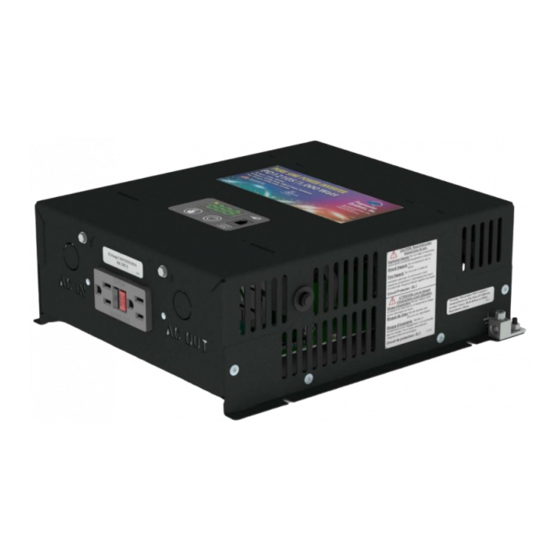
Installation and Operation Guide for
PD1200 Series Pure Sine Wave Inverters
Member
The PD1200 Series Inverter is a 120 VAC, 60 Hz, pure sine wave inverter with integrated transfer switch. It has been robustly designed
with safety and protection features for installation in recreational and commercial vehicles. With a built in transfer switch this inverter can
switch seamlessly between inverter power and external shore power without any power interruptions. It has been UL certified in both the
US and Canada so you can feel comfortable knowing that your inverter is safe.
With the addition of the PD1200 Series Inverter, Progressive Dynamics, Inc. has a complete line of power products for your commercial
and recreational vehicle needs. PDI has existing product lines of Power Converters, Automatic Transfer Switches, AC Distribution Panels,
and DC Distribution Panels. These product lines along with the newly introduced inverter make Progressive Dynamics the only part sup-
plier you need to build a complete power system for your recreational or commercial vehicle. Our experienced sales and service department
are available to help determine which power solutions are best suited to your needs.
© 2018 Progressive Dynamics Enterprises, LLC. All rights reserved.
701559 Rev. C
Advertisement

Subscribe to Our Youtube Channel
Related Manuals for Progressive Dynamics PD1210SV


Summary of Contents for Progressive Dynamics PD1210SV
- Page 1 US and Canada so you can feel comfortable knowing that your inverter is safe. With the addition of the PD1200 Series Inverter, Progressive Dynamics, Inc. has a complete line of power products for your commercial and recreational vehicle needs. PDI has existing product lines of Power Converters, Automatic Transfer Switches, AC Distribution Panels, and DC Distribution Panels.
-
Page 2: Table Of Contents
Technical Specifications ................16 LIMITED WARRANTY LIMITED WARRANTY: Progressive Dynamics Warrants its power inverters to be free from defects in material or workmanship under normal use and ser- vice; and limits the remedies to repair or replacement. DURATION: This warranty shall extend for a period of two years from the original date of purchase, and is valid only within the continental limits of the United States and Canada. -
Page 3: Introduction
Inverter with Optional Remote & GFCI Materials (1) PD1200 Series Inverter (1) Quick Reference Guide—not shown (1) Remote Display—not shown (optional) (1) Remote Display Connection Cable (optional) NOTE: If any of the items are missing, contact Progressive Dynamics for replacement. - Page 4 Introduction Figure 2 Figure 3 PD1200 Series Inverter (DC End View) PD1200 Series Inverter (AC End View) Figure 4 PD1200 Series Inverter (Side View) Figure 5 PD1200 Series Inverter (Isometric View) Descriptions DC Input Port (negative): Used to connect to battery (-) Ventilation Input: Ensure ventilation input is not blocked for proper operation DC Input Port (positive):...
-
Page 5: Key Features
Thermally-Controlled Variable Speed Fan The PD1200 Series Inverter is capable of being used with a hard- Using technology that is found in all Progressive Dynamics Convert- wired output. In installations designed to use this hard-wired output ers, the PD1200 Series Inverter employs a thermally-controlled vari- there isn’t a need to select the optional Ground Fault Circuit Inter-... -
Page 6: Rv Power System
The PD1200 Series Inverter in a 30A RV Power System PD60 SERIES DC GROUND TO DC LOADS DC DISTRIBUTION PANEL GROUND SHORE CONNECTION PD9200 SERIES CONVERTER 12V BATTERY BANK GENERATOR PD1200 SERIES INVERTER GENERATOR SHORE PANEL PD51 SERIES TRANSFER SWITCH GROUND AC IN AC OUT... - Page 7 The PD1200 Series Inverter in a 50A RV Power System PD60 SERIES DC GROUND TO DC LOADS DC DISTRIBUTION PANEL GROUND GENERATOR SHORE CONNECTION PD9200 SERIES CONVERTER Battery Bank PD1200 SERIES INVERTER GROUND PD52 SERIES AC IN AC OUT TRANSFER SWITCH GROUND MAIN NEUTRAL SUB NEUTRAL...
- Page 8 Choosing a Location For Your Inverter Installation Location Requirements The PD1200 series inverter should only be installed in locations that meet the following requirements: Dry: The inverter should be installed in a compartment separated from the outside environment to avoid exposure to rain, drips, and splashes that may damage the unit.
- Page 9 Mounting Instructions Mounting Instructions 1. Remove the PD1200 series inverter from its packaging, verify that all components are present, and record the inverter serial number in the quick reference guide contained within. 2. Select an appropriate mounting location and orientation (See Page 8 for additional details regarding acceptable installation practices). 3.
- Page 10 AC Connection Instructions AC Input AC Wiring Cover GFCI Output (Optional) AC Output Figure 9 AC Connections Side View Hardwired AC Connection Instructions NOTE: Hardwired AC connection is not necessary. To avoid un-necessary debris, only remove knockouts if your installation requires use of the AC hardwired connections.
-
Page 11: Installation Instructions
Types of AC Strain Reliefs The PDI inverter includes knockouts for use with a standard 3/8” trade size strain relief. Use of a strain relief is required when hard wiring your inverter. Neglecting to use a strain relief may cause undue stress and fatigue to the wiring connections on your unit. PDI lists examples of some commonly utilized types of strain relief. - Page 12 DC Connection Instructions Torque ground lug to 30-50 In-lbs Equipment Ground Cable (not included) 3/4” 3/4” DC cable (Positive) Figure 12 Connecting the Grounding Cable Equipment Ground Lug Negative DC Lug DC Wiring Cover Positive DC Lug 3/4” DC cable (Negative) Figure 13 Figure 14 DC Connections Side View...
-
Page 13: Display And User Interface
Display Interface Select Button Display Power Button Remote Display Port Display Panel Figure 17 Display Panel ERROR CODES Figure 16 Inverter Display Location Error Code Condition Description Low battery volt- Input voltage has dropped beneath 10.5V for Display Features age detected several seconds. - Page 14 Display Operation DC Input Voltage Battery indicator is illuminated Volts indicator is illuminated DC Input Voltage measurement is always available DC Input Voltage measurement is the default display state on start up AC Output Voltage AC indicator is illuminated ...
-
Page 15: Troubleshooting
Troubleshooting Troubleshooting Guide Symptom Corrective Actions The inverter has detected a fault condition (see Figure 20). 30 Seconds after the fault condition is detected the display enters PD1200 Series In- sleep mode. verter has a flashing Press the select button to view the error code. Press the select button again to view the battery voltage. Proceed to the fault light correct troubleshooting action below. -
Page 16: Technical Specifications
Troubleshooting Troubleshooting Guide Symptom Corrective Actions During startup the inverter draws a small amount of current to charge the input capacitors. If that current exceeds a normal range the inverter shuts down and reports an internal error. This is can be indicative of bad input wiring or an internal failure. E-5 is displayed ...
Need help?
Do you have a question about the PD1210SV and is the answer not in the manual?
Questions and answers