Advertisement
Quick Links
LUXOMAT
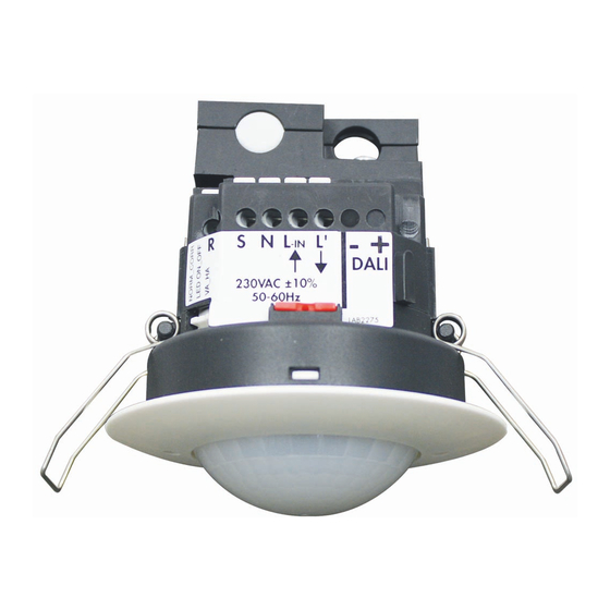
Installation and Operating Instruction for B.E.G. - Occupancy detector PD2-M-DALI/DSI-1C-FC
1. Product information
•
O ccupancy detector for daylight-dependent lighting
control
•
D ALI/DSI interface for controlling digitally dimmable
electronic ballasts as a group
•
O ne additional switching channel for controlling lights
and HVAC (heating, ventilation, air conditioning) devices
•
S witching between DSI and DALI program by remote
control or DIP switch
•
E xtension of the detection area by Slave devices is
possible
•
S et value brightness, follow-up time – LIGHT/HVAC and
orientation light adjustable
•
Manual switching and dimming via pushbutton possible
•
Orientation light function
2. Operation
The presence detector controls the light automatically according
to people present (movements) and the ambient brightness.
The integrated light sensor constantly measures the ambient light
and compares it with the set value brightness on the detector. If
the ambient light is sufficient, lighting will not be switched.
If the ambient light level is below the set value brightness, a
movement activates the lighting in the room.
The detector switches the light off despite of a person being pre-
sent if there is enough natural light for 5 min or if no movement
is detected for one follow-up time.
3. Safety information
R2
40
Work on the 110-240 V mains supply may only be
50
30
60
60
15
carried out by qualified professionals or by instructed
120
5
A
persons under the direction and supervision of quali-
!
fied skilled electrical personnel in accordance with
electrotechnical regulations.
Disconnect supply before installing!
This device is not suitable for disconnection.
Mounting the cover ring, after introduction of the
power cable (FC version).
4. Mounting
In Master/Slave operation the Master device must
!
always be installed at the site with less daylight.
The light sensor should be mounted on the opposite
!
side of the window.
68 mm
A circular opening of diameter 68 mm must be produced in the
ceiling. Having connected up the cables in accordance with
regulations, the detector is inserted into the opening as shown in
the drawing and fixed into position with the assistance of the
spring clips.
®
5. Position DIP switches, LEDs and
Potentiometers
Light
measurement
6. Self test cycle/Startup behavior
The product enters an initial 60-second self-test cycle, when the
supply is first connected. During this time the device does not
respond to movement and stays on.
7. Putting into operation / Settings
20%
R1
LUX
2000
1200
50 30
600
10
18 16
10
5
6
200
22
3
25
40
1
30
TE
R2
20%
R1
40
50 30
30
10
18 16
50
10
5
60
15
6
60
22
3
25
120
5
1
30
A
TE
R2
20%
40
50 30
30
10
50
5
60
15
60
120
5
A
R2
40
30
50
15
60
120
5
A
A
!
PD2-M-DALI/DSI-1C
LEDs
II III
I
D
A
B
C
PD2
3
2
False ceiling
mounting
Brightness value for constant light control
(Potentiometer A)
The brightness set value can be defined between
10 and 2000 lux. The potentiometer enables a free
selection of the brightness value.
Symbol : Night-time operation
Symbol
: D ay-time operation
(Light evaluation inactive)
Follow-up time for light control (Potentiometer B)
LUX
2000
The follow-up time can be set to 1 to 30 minutes.
1200
600
200
Symbol TEST: test mode
40
Irrespective of the brightness, every movement switches
the light on for 1s, then off again for 2s.
Follow-up time for orientation light (Potentiometer C)
The follow-up time can be set infinitely variably at
R1
LUX
2000
between 5 and 60 minutes. Manually switching ON/
1200
18 16
600
10
OFF the orientation light.
6
200
22
3
25
40
"ON" for permanent orientation light
1
30
TE
"OFF" for deactiviation of orientation light
Follow-up time for device control (Potentiometer D)
20%
R1
LUX
The follow-up time can be adjusted between 5 min. and
2000
1200
120 min. The delay is active from a set time of >15 mi-
50 30
18 16
600
10
10
5
60
6
nutes. This delay is about 5 min. If no other movements
22
3
25
1
are detected during this time, the delay starts again.
30
TE
Impulse function
The impulse function can be used to control external
HVAC systems. All 9 sec. will be set an impulse of
2.5 sec.
Alarm impulse
In order to initiate an alarm impulse, there have to be
three detected movements within a period of 9 sec.
This function can be used to display a presence in the
room on external visualizations. All 9 sec. will be set an
impulse of 2.5 sec.
The device does not fulfil the requirements of DIN
EN50131-2-2 and therefore cannot be used in
professional intrusion detection systems.
DIP switch functions
DIP 1
Full automatic mode
DIP 2
HVAC function
DIP 3
Operation mode DALI
* I f you select "LIGHT", the switching relay R2 operates synchro-
nously to the DALI light channel. The potentiometer R2 has no
function in this setting.
Potentiometer A Brightness (constant light control) channel 1
Potentiometer B Follow-up time (light) channel 1
Potentiometer C Follow-up time (orientation light)
Potentiometer D Follow-up time (device control) channel 2
LED I green
1
LED II red
LED III white
8. Wiring diagram
Standard mode with Master/Slave
L
N
T1
M1
S
N
L
L'
Master
9. Manual switching and dimming
By pressing the push button, the phase can be given to the S
terminal.
To turn on or off the light, press the push button briefly. The light
will remain on or off, as long as people are detected plus the
follow-up time.
With a long press of the push button the light will be dimmed
manually. When releasing the button, the current brightness value
is retained.
With renewed long press of the push button, the dimming direction
is reversed.
Taking the phase to the R terminal by using a button, the HVAC
channel can be switched with a short key press.
200
40
10. Range
2.50 m
1
quer zum Melder gehen
Walking across
2
frontal zum Melder gehen
Walking towards
Seated
Unterkriechschutz
Connected Slave devices must have the same phase
!
as the Master device.
EN
Semi-automatic mode
Light control*
Operation mode DSI
L
N
E1
DALI/DSI
DA
DA
T2
+
-
R
R
N
L
DA1
Slave
2
1
Advertisement

Related Manuals for B.E.G. LUXOMAT PD2-M-DALI/DSI-1C


Summary of Contents for B.E.G. LUXOMAT PD2-M-DALI/DSI-1C
- Page 1 LUXOMAT ® PD2-M-DALI/DSI-1C Installation and Operating Instruction for B.E.G. - Occupancy detector PD2-M-DALI/DSI-1C-FC 1. Product information 5. Position DIP switches, LEDs and DIP switch functions Potentiometers • O ccupancy detector for daylight-dependent lighting DIP 1 Full automatic mode Semi-automatic mode LEDs control II III DIP 2 HVAC function Light control* •...
- Page 2 13. Article / Part nr. / Accessory by a short press of • setting the potentiometers to “TEST“ and ”SUN” (see the button section 24), or • p ressing the “Reset” button on the remote control in Exit programming mode open state If there is no entry for PD2-M-DALI/DSI-1C (Master) 92486 about 3 min. the programming PD2-S (Slave) 92166 LUXOMAT IR-PD-DALI-1C ® mode is ended automatically. LUXOMAT Remote control: ®...
- Page 3 17. Light regulation 21. 100 h function The detector has two different integrated light control algorithms. (long press (> 3 sec.) when closed) The set value for the first algorithm is adjusted by potentiometer (LUX) on the device. Very small light amounts, which shine Before the lamp can be dimmed, the dimming function has directly to the detector, have as result that the set value brightness to be suppressed for a certain time in order to burn in the is exceeded. lamps. The second algorithm has an integrated daylight compensation. T5 fluorescent lamps: 80 h Therefore, it is necessary that the detector analyses the switched T8 fluorescent lamps: 100 h light quantity. This algorithm can only be used by remote control. For activating the function, press button “Light ON/OFF” in closed The programming of the set value and the measurement of the state. During this time, the detector only switches the light ON or light quantity is carried out in two steps: OFF. A dimming to the set value does not take place. After having activated the function, the red and green LED flash alternately. In the open state By pressing the button “Light ON/OFF” again, it is possible to 1500 deactivate the function before the time has elapsed. • The set value is adjusted without daylight (please darken the room) by using the remote control. Failure to comply to the burn-in would lead to reducing the life of the lamp. A further disadvantage could be unwanted random vari- •...