Table of Contents
Advertisement
Quick Links
UNVENTED (VENT FREE) GAS LOG HEATER
OWNER'S OPERATION AND INSTALLATION MANUAL
Vent Free Models Also Design-Certified As Vented Decorative Appliances
WARNING: If the information in this manual is not
followed exactly, a fire or explosion may result causing
property damage, personal injury or loss of life.
— Do not store or use gasoline or other flammable
vapors and liquids in the vicinity of this or any other
appliance.
— WHAT TO DO IF YOU SMELL GAS
• Do not try to light any appliance.
• Do not touch any electrical switch; do not use any
phone in your building.
• Immediately call your gas supplier from a neighbor's
phone. Follow the gas supplier's instructions.
• If you cannot reach your gas supplier, call the fire
department.
— Installation and service must be performed by a quali-
fied installer, service agency or the gas supplier.
INSTALLER: Leave this manual with the appliance.
CONSUMER: Retain this manual for future reference.
For more information, visit www.desatech.com
MODELS VFRMV18NB, VFRMV18PB,
VFRMV24NB AND VFRMV24PB
O-TL REPORT
# 258-L-17-5
ANSI Z21.11.2b-2008
ANSI Z21.60b-2004
APPROVED
Advertisement
Table of Contents

Related Manuals for Vanguard Firewerks VFRMV18NB


Summary of Contents for Vanguard Firewerks VFRMV18NB
- Page 1 O-TL REPORT # 258-L-17-5 UNVENTED (VENT FREE) GAS LOG HEATER OWNER’S OPERATION AND INSTALLATION MANUAL ANSI Z21.11.2b-2008 ANSI Z21.60b-2004 APPROVED MODELS VFRMV18NB, VFRMV18PB, VFRMV24NB AND VFRMV24PB Vent Free Models Also Design-Certified As Vented Decorative Appliances WARNING: If the information in this manual is not followed exactly, a fire or explosion may result causing property damage, personal injury or loss of life.
-
Page 2: Table Of Contents
TABLE OF CONTENTS Safety ..............2 Wiring Diagram ..........20 Product Identification ........... 5 Cleaning and Maintenance ........ 21 Local Codes............5 Troubleshooting ..........22 Unpacking............5 Specifications ............ 26 Optional Remote Control Accessories ....5 Replacement Parts ..........26 Product Features .......... - Page 3 SAFETy Continued IMPORTANT: Read this owner’s WARNING: Do not allow fans manual carefully and completely to blow directly into the fireplace. before trying to assemble, op- Avoid any drafts that alter burner erate or service this log set. flame patterns. Ceiling fans can Improper use of this log set can create drafts that alter burner cause serious injury or death...
- Page 4 SAFETy Continued 7. To prevent the creation of soot, follow the Keep the appliance area clear instructions in Cleaning and Maintenance, and free from combustible ma- page 21. terials, gasoline and other flam- 8. Before using furniture polish, wax, carpet mable vapors and liquids.
-
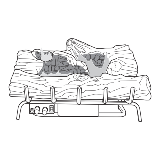
Page 5: Product Identification
PRODUCT IDENTIFICATION Log Set Chassis Assembly Figure 1 - Product Identification LOCAL CODES Install and use the heater with care. Follow Standard CAN/CSA Z240 MH, Standard, Title all local codes. In the absence of local codes, 24 CFR, Part 3280, in the United States or use the latest edition of the National Fuel Gas when such a Standard is not applicable, ANSI/ Code ANSI Z223.1/NFPA 54*... -
Page 6: Product Features
PRODUCT FEATURES OPERATION SAFETY DEVICE This heater is clean burning. It requires no This heater has a pilot with an Oxygen Deple- outside venting. There is no heat loss out a tion Sensing (ODS) safety shut off system. vent or up a chimney. Heat is generated by The ODS/pilot is a required feature for vent- both realistic flames and glowing coals. - Page 7 AIR FOR COMBUSTION AND VENTILATION Continued Confined and Unconfined Space Vent-free appliance _______ Btu/Hr The National Fuel Gas Code, ANSI Z223.1/ Gas water appliance* _______ Btu/Hr NFPA 54 defines a confined space as a space Gas furnace _______ Btu/Hr whose volume is less than 50 cubic feet per Vented gas appliance _______ Btu/Hr 1,000 Btu/hr (4.8 m per kw) of the aggregate...
- Page 8 AIR FOR COMBUSTION AND VENTILATION Continued the ceiling and one within 12" of the floor on WARNING: If the area in which the wall connecting the two spaces (see op- the heater may be operated does tions 1 and 2, Figure 2 on page 8). You can also remove door into adjoining room (see not meet the required volume for option 3, Figure 2).
-
Page 9: Installation
INSTALLATION NOTICE: This heater is intended WARNING: Seal any fresh for use as supplemental heat. air vents or ash clean-out doors Use this heater along with your located on floor or wall of fire- primary heating system. Do not place. If not, drafting may cause install this heater as your primary pilot outage or sooting. - Page 10 INSTALLATION Continued CHECK GAS TYPE Example: The face of a mantel, bookshelf, etc. is made of combustible material must Use the correct gas type (natural or propane/ be 4" from the side of the fireplace to the LP) for your unit. If your gas supply is not cabinet (see Figure 4).
- Page 11 INSTALLATION Continued If Using Mantel Mantel Shelf 10" You must have noncombustible material(s) 8" Underside of above the fireplace opening. Noncombus- 6" Mantel Shelf " tible materials (such as slate, marble, tile, etc.) must be at least 1/2" thick. With sheet metal, you must have noncombustible ma- All minimum distances...
- Page 12 INSTALLATION Continued NOTICE: Surface temperatures of adjacent walls and mantels become hot during operation. Walls and mantels above the Hearth Combustible firebox may become hot to Material 5" the touch. If installed properly, Min. these temperatures meet the requirement of the national Figure 9 - Minimum Fireplace Clearances Above Combustible Flooring product standard.
- Page 13 INSTALLATION Continued damper. You must install the damper clamp INSTALLING HEATER ASSEMBLY accessory (to order, see Accessories, page WARNING: If installing in a 27). This will insure vented operation (see Figure 10, page 12). The damper clamp will sunken fireplace, special care is keep damper open.
- Page 14 INSTALLATION Continued CONNECTING TO GAS SUPPLY damage could occur. Install external regulator with the vent pointing down as shown in Figure WARNING: This appliance 13. Pointing the vent down protects it from freezing rain or sleet. requires a 3/8" NPT (National Pipe Thread) inlet connection to CAUTION: Use only new, the pressure regulator.
- Page 15 INSTALLATION Continued Installation must include an equipment shutoff CAUTION: Make sure exter- valve, union and plugged 1/8" NPT tap. Locate nal regulator has been installed NPT tap within reach for test gauge hook up. NPT tap must be upstream from heater (see between propane/LP supply Figure 14, page 14).
-
Page 16: Operation
INSTALLATION Continued Equipment 3. Check all joints from gas meter to equip- Propane/LP Shutoff Valve Supply Tank ment shutoff valve for natural gas or propane/LP supply to equipment shutoff valve for propane/LP (see Figure 16 or 17). Apply noncorrosive leak detection fluid to all joints. - Page 17 OPERATION Continued LIGHTING WARNING: Burners will come INSTRUCTIONS on automatically within one min- WARNING ute when the switch is in the ON • If fireplace has glass doors, position after the pilot is lit. never operate this heater with 5. Wait five (5) minutes to clear out any gas. glass doors closed.
- Page 18 OPERATION Continued 11. Set flame adjustment knob to any level OPTIONAL HAND-HELD between HI and LO. REMOTE OPERATION 12. To leave pilot lit and shut off burners only: Note: All remote control accessories must turn control knob clockwise to the be purchased separately (see Accessories, PILOT position, or use remote control page 27).
- Page 19 OPERATION Continued Turns Hand- Digital Display Shows Held Remote Temperature and Settings On or Off and Control Allows You Indicator Button to Choose Light AUTO the Manual ROOM Locks TEMP TEMP Setting System to Prevent TEMP LOCK POWER Accidental Ignition MANU AUTO ºC/ºF...
-
Page 20: Inspecting Burners
INSPECTING BURNERS Check pilot flame pattern and burner flame If burner flame pattern is incorrect, as shown patterns often. in Figure 26 • turn heater off (see To Turn Off Gas to Ap- PILOT FLAME PATTERN pliance, page 18) Figure 23 shows a correct pilot flame pattern. •... -
Page 21: Cleaning And Maintenance
CLEANING AND MAINTENANCE 5. Blow air into the primary air opening on WARNING: Turn off heater the injector holder. 6. In case any large clumps of dust have now and let cool before cleaning. been pushed into the burner repeat steps 3 and 4. -
Page 22: Troubleshooting
TROUBLESHOOTING WARNING: Turn off and unplug heater and let cool before servicing. Only a qualified service person should service and repair heater. CAUTION: Never use a wire, needle or similar object to clean ODS/pilot. This can damage ODS/pilot unit. Note: All troubleshooting items are listed in order of operation. OBSERVED PROBLEM POSSIBLE CAUSE REMEDY... - Page 23 TROUBLESHOOTING Continued OBSERVED PROBLEM POSSIBLE CAUSE REMEDY ODS/pilot lights but flame 1. Control knob not fully 1. Press in control knob fully goes out when control knob pressed in is released 2. Control knob not pressed in 2. After ODS/pilot lights, keep long enough control knob pressed in 30 seconds...
- Page 24 TROUBLESHOOTING Continued OBSERVED PROBLEM POSSIBLE CAUSE REMEDY Orange flame in burner during 1. Not enough air 1. Check burner(s) for dirt burner combustion and debris. If found, clean burner(s) (see Cleaning and Maintenance, page 21) 2. Gas regulator defective 2. Replace gas regulator Slight smoke or odor during 1.
- Page 25 TROUBLESHOOTING Continued WARNING: If you smell gas • Shut off gas supply. • Do not try to light any appliance. • Do not touch any electrical switch; do not use any phone in your building. • Immediately call your gas supplier from a neighbor’s phone. Fol- low the gas supplier’s instructions.
-
Page 26: Specifications
SPECIFICATIONS VFRMV18NB VFRMV24NB • Rating (Variable): 20,000/30,000 Btu/Hr • Rating (Variable): 24,000/36,000 Btu/Hr • Gas Type: Natural Gas Only • Gas Type: Natural Gas Only • Ignition: Piezo • Ignition: Piezo • Manifold Pressure: 3.5" W.C. - 1.6" W.C. • Manifold Pressure: 3.5" - 1.6" W.C. •... -
Page 27: Accessories
ACCESSORIES WALL-MOUNT ON/OFF SWITCH Purchase these accessories from your local dealer. If they can not supply these accessories GWMS2 call DESA Heating, LLC at 1-866-672-6040 for For all models. Allows the gas log heater to information. You can also write to the address be turned on and off with a wall switch. -
Page 28: Parts
PARTS MODELS VFRMV18NB, VFRMV18PB, VFRMV24NB (Shown) AND VFRMV24PB www.desatech.com 116412-01E... - Page 29 PARTS LIST This list contains replaceable parts used in your heater. When ordering parts, follow the instructions listed under Replacement Parts on page 26 of this manual. NO. PART NO. DESCRIPTION QTY. Grate Assembly • • • • 111800-01 Screw •...
- Page 30 NOTES _____________________________________________________ ______________________________________________________ ______________________________________________________ ______________________________________________________ ______________________________________________________ ______________________________________________________ ______________________________________________________ ______________________________________________________ ______________________________________________________ ______________________________________________________ ______________________________________________________ ______________________________________________________ ______________________________________________________ _____________________________________________________ ______________________________________________________ ______________________________________________________ ______________________________________________________ ______________________________________________________ ______________________________________________________ ______________________________________________________ ______________________________________________________ ______________________________________________________ ______________________________________________________ ______________________________________________________ ______________________________________________________ ______________________________________________________ _____________________________________________________ ______________________________________________________ ______________________________________________________ ______________________________________________________ ______________________________________________________ ______________________________________________________ ______________________________________________________ ______________________________________________________ ______________________________________________________ www.desatech.com 116412-01E...
- Page 31 NOTES _____________________________________________________ ______________________________________________________ ______________________________________________________ ______________________________________________________ ______________________________________________________ ______________________________________________________ ______________________________________________________ ______________________________________________________ ______________________________________________________ ______________________________________________________ ______________________________________________________ ______________________________________________________ ______________________________________________________ _____________________________________________________ ______________________________________________________ ______________________________________________________ ______________________________________________________ ______________________________________________________ ______________________________________________________ ______________________________________________________ ______________________________________________________ ______________________________________________________ ______________________________________________________ ______________________________________________________ ______________________________________________________ ______________________________________________________ _____________________________________________________ ______________________________________________________ ______________________________________________________ ______________________________________________________ ______________________________________________________ ______________________________________________________ ______________________________________________________ ______________________________________________________ ______________________________________________________ 116412-01E www.desatech.com...
-
Page 32: Warranty
WARRANTy kEEP THIS WARRANTy Model (located on product or identification tag) _____________________________ Serial No. (located on product or identification tag) __________________________ Date Purchased __________________________ Keep receipt for warranty verification. DESA HEATING, LLC LIMITED WARRANTIES New Products Standard Warranty: DESA Heating, LLC warrants this new product and any parts thereof to be free from defects in material and workmanship for a period of four (4) years from the date of first purchase from an authorized dealer provided the product has been installed, maintained and operated in accordance with DESA Heating, LLC’s warnings and instructions.
Need help?
Do you have a question about the Firewerks VFRMV18NB and is the answer not in the manual?
Questions and answers