
Subscribe to Our Youtube Channel
Related Manuals for Siemens SDR 15.5


Summary of Contents for Siemens SDR 15.5
- Page 1 Instruction manual Type SDR 15.5 kV to 27 kV triple-single distribution recloser Installation operation maintenance E50001-F710-A412-X-4A00 Answers for infrastructure.
- Page 2 50 volts or more, and shall, Siemens reserves the right to make changes at a minimum, be additionally trained in all of in the specifications shown herein or to make...
-
Page 3: Table Of Contents
Siemens Industry, Inc. The warranty contained in the contract between Annex A 38 – 39 the parties is the sole warranty of Siemens Industry, Inc. Any statements contained herein do not create new warranties or modify the existing warranty. -
Page 4: Introduction
Any other use is forbidden, unless the and use of the equipment. consent of Siemens has been obtained. Personnel must familiarize themselves as If the above-mentioned conditions are not early as possible with the instructions and... - Page 5 Siemens field service at +1 (800) 347-6659 or +1 (919) 365-2200 outside the U.S. For medium voltage customer service issues, contact Siemens at +1 (800) 347-6659 or +1 (919) 365-2200 outside the U.S.
-
Page 6: General Description
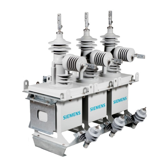
General description Recloser principle and design The manufacture, design and testing of the vacuum recloser is based on current Reclosers are used in distribution systems. regulations and standards and state-of-the- Like circuit breakers, reclosers are used to art technology. The product conforms to the make and break normal and fault currents. - Page 7 1. Pole with integrated vacuum interrupter 2. Position indicator (underneath) 3. Operating mechanism housing 4. Lower terminal (usually load side) 5. Upper terminal (usually line side) 6. Lockout handle Figure 1: Single-phase recloser switch unit (front view) 1. Pole with integrated vacuum interrupter 2.
- Page 8 1. Vertical brace assembly 2. Upper lifting eye 3. Upper terminal surge arrester bracket (optional) 4. Lower terminal surge arrester bracket (optional) 5. Leveling feet Figure 3: Typical triple-single close-coupled pole mounting front view 1. Vertical brace assembly 2. Pole channel 3.
- Page 9 Siemens controllers. If a phase electrically, whether locally or from a non-Siemens controller is used, it is the remote location. The interlocking is not reset controller vendor’s obligation to properly...
- Page 10 Triple-single frame [PCB3] are not utilized). poles. Only the Siemens type 7SR224 control and For installation within a substation, a special protection relay option is illustrated in this mounting frame is available. instruction manual.
- Page 11 Triple-single type SDR controller 1. Door The triple-single type SDR controller is 2. Triple-single type SDR equipped with integrated pole-mount controller brackets. It can be installed on the recloser 3. Pole-mount bracket pole or substation frame at an operating 4. Type 7SR224 control and height as preferred by the user.
- Page 12 Figure 13: Connector mounting plate, control cable connector, 1. Connector mounting plate voltage sensor connector and 2. Control cable connector optional antenna or auxiliary power connection 3. Optional voltage sensor connector 4. Optional auxiliary power connection 5. Optional antenna connector provision Figure 14: Optional vandal guard 1.
- Page 13 A. Capacitor discharge switch B. J1 - jumper 1, pins 1-2 C. J2 - jumper 2, pins 1-2 D. J3 - jumper 3, pins 1-2 E. J4 - jumper 4, pins 1-2 Pin position Pin position Figure 17: PCB2 jumpers Hazardous voltage.
- Page 14 Auxiliary power supply Deep discharge protection (provided with the Siemens type 7SR224 control and The triple-single type SDR controller uses an protection relay) internal 48 V bus, which is backed-up by rechargeable batteries as an uninterruptible The controller is equipped with deep power supply.
-
Page 15: Receiving, Handling And Storage
Introduction 3. Notify the Siemens field service at +1 (800) 347-6659 or +1 (919) 365- This portion of the manual covers the 2200 outside the U.S. - Page 16 Storage procedure Space heating Whenever possible, store the recloser Space heating for the controller must be indoors. The storage environment must be used for both indoor and outdoor storage to clean, dry and free of such items as: prevent condensation and corrosion. The construction dust, corrosive atmosphere, controller space heater should be connected mechanical abuse and rapid temperature...
-
Page 17: Installation And Commissioning
Installation and commissioning Hazardous voltages. Will cause death, serious injury or property damage. To avoid electrical shock or burns, this equipment must be installed, operated and maintained only by qualified persons thoroughly familiar with the equipment, instruction manuals and drawings. Heavy weight. - Page 18 Preparatory work Mechanical installation The following documents are required for Both the installation and commissioning report (see page 32) and these installation installation: instructions are based on the sequence of the These operating instructions work to be performed. The on-site conditions may result in deviations from the sequence Order specific drawings shown.
- Page 19 Installation of the triple-single type SDR Connection covers controller on the pole The control and (optional) voltage sensor To attach the triple-single type SDR controller cable connections are supplied with covers at the following components are required: the recloser switch unit and the controller. When connecting the cables, the covers Two 0.75 inch mounting bolts with nuts should be stored in a clean and dry...
- Page 20 1. Recloser switch units 2. Surge arrester load side (optional) 3. Ground terminal (switch unit) 4. Ground connection for surge arrester (optional) 5. Ground wire 1. Connector for auxiliary power 6. Control cable supply (optional) 7. Triple-single type SDR controller 2.
- Page 21 Annex A on page 38. external transformer or an external low-voltage power supply. In both cases, Only the Siemens type 7SR224 control and insert the connection cable through the cable protection relay option is illustrated in this gland (see Figure 22: Triple-single type SDR instruction manual.
-
Page 22: Operation
Operation Operation Switching The recloser is just one device in a distribution Switching comprises electrical switching system. The user of the recloser must set the (remote and/or local operation) and controller protection and control parameters mechanical switching (by means of the to suit the user’s distribution system needs, lockout handles). - Page 23 Modes of operation The recloser pole opens. By operating the lockout mechanism, the recloser pole is The type SDR triple-single recloser has three opened mechanically and locked in this modes of operation: position. Mode A, 3P Trip/3P LO allows the three The mechanical position indicator on the single-pole reclosers to operate in the bottom of the recloser switch unit pole...
- Page 24 Table 2: Troubleshooting Malfunction Remedy The auxiliary power supply is protected by a miniature circuit breaker in the front of the swing panel. Failure of the auxiliary power supply (for example, "Aux power OK" LED 1. Check miniature circuit breaker CB1 and switch on if necessary. does not light up).
-
Page 25: Maintenance
Maintenance Hazardous voltages. Will cause death, serious injury or property damage. Always de-energize and ground the equipment and all terminals before performing any work near high-voltage conductors. Work on the recloser switch unit or the control cubicle should be performed only by qualified personnel. Do not open the inner panel of the control cubicle, as interior parts energized at voltages higher than 50 V are present. - Page 26 On request Animal guards On request Set of terminal connectors (six pieces) On request Set of batteries (four batteries, 12 Ah, 48 V) On request Heaters On request Type SDR 15.5 kV to 27 kV triple-single distribution recloser instruction E50001-F710-A412-X-XXXX manual...
-
Page 27: Technical Data
Technical data Table 5: Main characteristic data Characteristic Unit Voltage class Rated maximum voltage U 15.5 27.0 Rated continuous current I 630, 800 630, 800 Rated lightning impulse withstand voltage U Power frequency insulation level withstand test voltage (one minute dry) U Rated symmetrical interrupting current I 12.5, 16 12.5... - Page 28 Current transformer data Altitude correction factor The current transformer has a ratio of The insulating capability of insulation in air 800:1. The accuracy is 0.5 VA 5P20 to IEC decreases as the altitude increases due to the 60044-1. reduced air density. The rated lightning impulse withstand voltage values (see Table Voltage sensor data (optional) 5) are valid according to IEC 62271-1 and...
- Page 29 Rated voltage U Unit 15.5 kV and 27.0 kV Table 10: Switch unit dimensions and weights (without frame) Dimensions: length x width x height in (mm) 46.3 (1,176) x 26.9 (673) x 42.8 (1,087) Weight lbs (kg) 450 (204) Figure 31: Recloser switch unit dimensions in (mm) 1.
- Page 30 Rated voltage U All voltages Table 11: Controller Dimensions: length x width x height (without in (mm) 18.0 (457) x 14.0 (356) x 36.0 (914) pole-mount brackets) Weight (without batteries) lbs (kg) 150 (67) Figure 32: Controller dimensions in (mm) 1.
- Page 31 14. Product type/style Switch C Prod. Date 15. Sales order number 16. Sales item number 17. Switch type IEEE C37.60 MADE IN USA 18. Instruction manual code Order Code Instruction Manual No. Siemens Industry, Inc. 18-762-111-050 7000 Siemens Road, Wendell, NC 27591...
-
Page 32: Installation And Commissioning Report
Installation and commissioning report Installation and commissioning report The installation and commissioning report on the following pages is intended for using and copying as a checklist. - Page 33 Installation and commissioning report Type SDR distribution recloser User Siemens Type SDR Location Recloser type Contract number Serial number Rated maximum voltage (kV) Rated continuous current (A) Auxiliary voltage Rated short-circuit current (kA) Answers for infrastructure.
- Page 34 Compare the correct voltage of the recloser. (For example, compare the rated voltage of the recloser with the system A.07 voltage. Contact Siemens customer service if the voltage is incorrect at +1 (800) 347-6659 or +1 (919) 365-2200 outside the U.S.)
- Page 35 Table 14: Function checks Item Checklist Notes Switch on miniature circuit breakers: CB1 and CB3 (behind the panel): Start-up of controller is shown on display. "Protection healthy" LED lights green after approximately 30 seconds C.01 Status LED "AuxPower OK" lights up green Status LED "Recloser OK"...
- Page 36 Table 14: Function checks Item Checklist Notes (continued) Mechanical operation of the recloser by pulling the lockout handle for either phase A, B or C: Recloser opens for each phase LED next to the Close function button for each phase is no C.08 longer lit LED next to the Open function button for each phase lights up...
- Page 37 Item Checklist Notes Table 16 Other services E.01 Instruction manual available. E.02 Routine test records available. E.03 On-site instruction on recloser/controller. E.04 Order specific drawings are available. E.05 Type 7SR224 quick reference guide available. Table 17: Remarks Name Department Date Signature Table 18: Signatures Technician...
-
Page 38: Annex A
Annex A Vendor website information: Siemens type 7SR224 recloser control relay (standard control and protection relay option) http://www.energy.siemens.com/ us/en/power-distribution/reclosers/recloser- controller.htm Schweitzer Engineering Laboratories, Inc. type SEL-651R recloser control relay (includes internal power module and capacitors which operate the swich unit magnetic actuator;... - Page 40 All product designations may be trade- marks or product names of Siemens AG or supplier companies whose use by third parties for their own purposes could vio- late the rights of the owners..
Need help?
Do you have a question about the SDR 15.5 and is the answer not in the manual?
Questions and answers