Table of Contents
Advertisement
Quick Links
Advertisement
Table of Contents

Subscribe to Our Youtube Channel
Related Manuals for ThermoFisher Scientific Ozone Primary Standard 49iQPS


Summary of Contents for ThermoFisher Scientific Ozone Primary Standard 49iQPS
- Page 1 49iQPS Instruction Manual Ozone Primary Standard 117434-00 • 1Apr2020...
-
Page 3: Table Of Contents
Contents Chapter 1 Introduction ......................1-1 iQ Series Instrument Platform............. 1-1 Principle of Operation ................ 1-3 Specifications ..................1-5 Dimensions ..................1-6 Chapter 2 Installation and Setup ..................2-1 Unpacking and Inspection ..............2-1 ... - Page 4 Contents Predictive Diagnostics ..............3-47 Maintenance ................3-48 Preventive Maintenance .............. 3-49 Change Part ................3-51 Maintenance History..............3-52 File Sharing and Support ............. 3-53 iQ360 ..................3-54 Measurement Settings ..............3-57 Averaging Time ................
- Page 5 Contents Leak Test .................... 4-5 Optical Bench Cleaning ..............4-6 Chapter 5 Troubleshooting ....................5-1 Safety Precautions ................5-1 Troubleshooting Guide ............... 5-1 Chapter 6 Servicing ......................6-1 Safety Precautions ................6-1 ...
- Page 6 Contents Photometer Lamp Power Supply ........... 7-2 Ozonator DMC ................7-2 Ozonator Lamp Power Supply ............7-2 Common Electronics ................7-2 Power Supply ................... 7-5 Front Panel ..................7-5 I/O and Communication Components ..........7-5 ...
- Page 7 Contents Appendix C GNU Lesser General Public License ............. C-1 GNU Lesser General Public License ........... C-1 Thermo Scientific 49iQPS Instruction Manual...
-
Page 9: Chapter 1 Introduction
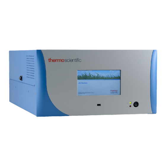
Chapter 1 Introduction The Thermo Scientific™ 49iQ Ozone Primary Standard utilizes UV Photometric technology to reliably produce ozone up to 1000 ppb in concentration. The 49iQ Ozone Primary Standard is a dual cell photometer, the concept adopted by NIST for the national ozone standard. The instrument can accurately generate up to 1000 ppb of ozone operating with ozonator flow rates between 3-4 liters per minute. -
Page 10: Figure 1-1. 49Iqps Front
Introduction iQ Series Instrument Platform experience to simplify daily operations. Custom designed ePort software allows remote access to the instrument with a PC. The ePort control mirrors the same GUI look and feel as the instrument touchscreen providing a speedy and familiar operational experience. Figure 1–1. -
Page 11: Principle Of Operation
Introduction Principle of Operation Principle of The 49iQPS operates on the principle that ozone (O ) molecules absorb UV light at a wavelength of 254 nm. The degree to which the UV light is Operation absorbed is directly related to the ozone concentration as described by the Beer-Lambert Law: ... -
Page 12: Figure 1-2. 49Iqps Flow Schematic
Introduction Principle of Operation Figure 1–2. 49iQPS Flow Schematic 49iQPS Instruction Manual Thermo Scientific... -
Page 13: Specifications
Introduction Specifications Specifications Table 1–1 lists the specifications for the 49iQPS. Table 1–1. 49iQPS Specifications Photometer Range 50–5000 ppb 100–10000 μg/m Zero Noise 0.25 ppb RMS (60 second averaging time) Detection Limit 0.5 ppb (60 second averaging time) Response Time 20 seconds (0–95%) Lag Time 10 seconds... -
Page 14: Dimensions
Introduction Dimensions Dimensions Figure 1–3. Bench Mount Assembly (dimensions in inches [mm]) 49iQPS Instruction Manual Thermo Scientific... -
Page 15: Figure 1-4. Rack Mount Assembly (Dimensions In Inches [Mm])
Introduction Dimensions Figure 1–4. Rack Mount Assembly (dimensions in inches [mm]) Thermo Scientific 49iQPS Instruction Manual... -
Page 16: Figure 1-5. Rack Mount Requirements
Introduction Dimensions Figure 1–5. Rack Mount Requirements Figure 1–6. Rack Requirements Part 2 49iQPS Instruction Manual Thermo Scientific... -
Page 17: Installation And Setup
Chapter 2 Installation and Setup Installation and Setup describes how to unpack, setup, and start-up the instrument. Equipment Damage Do not attempt to lift the instrument by the cover or other external fittings. ▲ Unpacking and The 49iQPS is shipped complete in one container. If there is obvious damage to the shipping container when you receive the instrument, notify Inspection the carrier immediately and hold for inspection. -
Page 18: Cover Removing And Replacing
Installation and Setup Cover Removing and Replacing Cover Removing Use the following procedure to remove and replace the cover. and Replacing Equipment required: Phillips screwdriver, #2 1. Unfasten the four 8-32 screws securing the cover (shipping screws). 2. Press in both latches located on top cover and hold while pulling up to remove. -
Page 19: Mounting Options
Installation and Setup Mounting Options Mounting The instrument can be installed in the following configurations: Options Bench Mount ● Rack Mount ● Bench Mount Positioned on bench, includes installing feet. See “Figure 2–2”. Equipment required: Slot drive, 5/16-inch 1. Fasten feet in position 1 or 2 to fit to the desired depth. Figure 2–2. -
Page 20: Rack Mount
Installation and Setup Mounting Options Rack Mount Mounting in a rack includes removing the front panel and installing ears and handles. Equipment required: Phillips drive, #2 1. Start by gripping from the top corners of the front panel and pull outwards. -
Page 21: Figure 2-4. Installing Ears And Handles
Installation and Setup Mounting Options Figure 2–4. Installing Ears and Handles Thermo Scientific 49iQPS Instruction Manual... -
Page 22: Setup Procedure
Installation and Setup Setup Procedure Setup Procedure Use the following procedure to setup the instrument: 1. Connect the zero air supply to the ZERO AIR bulkhead on the rear panel (Figure 2–5). Ensure that the sample line is not contaminated by dirty, wet, or incompatible materials. -
Page 23: Figure 2-5. 49Iqps Rear Panel
Installation and Setup Setup Procedure Figure 2–5. 49iQPS Rear Panel Figure 2–6. Atmospheric Dump Bypass Plumbing Thermo Scientific 49iQPS Instruction Manual... -
Page 24: Startup
Installation and Setup Startup Startup Use the following procedure when starting the instrument. 1. Turn the power ON. 2. Allow 90–120 minutes for the instrument to stabilize. During the time that the instrument is warming up, the mode “warm up” is displayed on the gas mode button in the title bar, and the concentration calculation is turned off. -
Page 25: Chapter 3 Operation
Chapter 3 Operation This chapter describes the functionality of the touchscreen user interface. Instrument The Instrument Display consists of a Title Bar, a User Interface, and a Status Bar. The Title Bar, located at the top, includes the Home button, Display instrument name, instrument gas mode, and Help button. - Page 26 Operation Instrument Display The Instrument Display contains the following information: Title Bar: ● Home button: When pressed, it brings you to the Home Screen. ● Title Text: Displays instrument name when in the Home Screen. ● Displays the chemical name, current concentration reading and unit when in all other screens.
- Page 27 Operation Instrument Display Thermo Scientific Information button: Shows contact information. ● Thermo Scientific 49iQPS Instruction Manual...
-
Page 28: Main Menus And Keypads
Operation Instrument Display Main Menus and The Main Menu buttons, located on the Home Screen, contains three submenus. Each submenu contains related instrument settings. This Keypads chapter describes each submenu and screen in detail. Refer to the appropriate sections for more information. Calibration Data Settings... -
Page 29: Numeric Keypad
Operation Instrument Display Numeric Keypad User enters a value into the box using the number keypad. When the user needs to change a value, such as for flow rates, temperatures or pressures, the keypad screen will automatically display. Initially, the box above the keypad will display the current value. -
Page 30: Alphanumeric Keypad
Operation Instrument Display Alphanumeric Keypad User enters a value into the box using the keypad. When the user needs to change an alphanumeric value, this keypad will automatically display. Initially, the box above the keypad will display the current value. Enter a new value using the keypad, and then select the Enter button to set the new value or press the Cancel button to exit the keypad screen and return to the previous screen without saving the value. - Page 31 Operation Instrument Display Thermo Scientific 49iQPS Instruction Manual...
-
Page 32: Calibration
Operation Calibration Calibration The Calibration screen is used to make minor compensations to the O concentration when the 49iQPS is being precisely matched to a NIST traceable O calibrator. Home Screen>Calibration The Calibration screen contains the following information: Adjust Background: Allows the user to adjust the zero background. ●... -
Page 33: Adjust Background
Operation Calibration Adjust Background The Adjust Background screen is used to make small adjustments to the zero level. This adjustment should only be made when the 49iQPS is being precisely matched to a NIST traceable O calibrator. Normally, the instrument does not require any background compensation. The user can manually adjust the zero background by entering a value in the Adjust Background button. -
Page 34: Adjust Span Coefficient
Operation Calibration Adjust Span The Adjust Span Coefficient screen is used to make small adjustments to the output level. This adjustment should only be made when the 49iQPS is Coefficient being precisely matched to a NIST traceable O calibrator. Normally, the instrument does not require any compensation. -
Page 35: Reset Bkg To 0.000 And Span Coef To 1.000
Operation Calibration Reset Bkg to 0.000 The Reset Bkg to 0.000 and Span Coef to 1.000 screen is used to reset the calibration configuration to factory defaults. and Span Coef to 1.000 Home Screen>Calibration>Reset Bkg to 0.000 and Span Coef to 1.000 The Reset Bkg to 0.000 and Span Coef to 1.000 screen contains the following information: Reset Bkg to 0.000 and Span Coef to 1.000: Resets all backgrounds and... -
Page 36: Custom O Levels
Operation Calibration Custom O Levels The Custom O Levels screen lists six custom levels: 1, 2, 3, 4, 5, and 6. Custom levels deal with ozonator control and configuration. A percentage of 100% results in the maximum amount of ozone production. A percentage of 0% results in no ozone production. -
Page 37: Calibration History
Operation Calibration Calibration History The Calibration History screen shows the log of calibrations and calibration checks performed. Use the and buttons to move up and down and the and buttons to move left and right. Home Screen>Calibration>Advanced Calibration>Calibration History Note Pressing the Calibration History button responds with Retrieving calibration log data, it may take a few seconds... -
Page 38: Data
Operation Data Data The Data screen is used to view and record concentrations and instrument data. Users can view both tabular data and graphed data. Home Screen>Data The Data screen contains the following information: View Data Log (Last Hour): User views last hour of historical data. ●... -
Page 39: View Data Log (Last Hour)
Operation Data View Data Log (Last The View Data Log (Last Hour) screen allows the user to instantly view the last hour worth of data in real time. Hour) Use the and buttons to move up and down and the and buttons to move left and right. -
Page 40: View Data Log (Last 24 Hours)
Operation Data View Data Log (Last The View Data Log (Last 24 Hours) screen allows the user to instantly view the last 24 hours worth of data in real time. 24 Hours) Use the and buttons to move up and down and the and buttons to move left and right. -
Page 41: View Data Log (User Defined Time)
Operation Data View Data Log (User The View Data (User Defined Time) screen is used to specify the start and end time for viewing the data logging table. Defined Time) Home Screen>Data>View Data Log (User Defined Time) Home Screen>Data>View Data Log (User Defined Time)>Save Data Logging Start Time The View Data Log (User Defined Time) screen contains the following information:... - Page 42 Operation Data The View Data Log (User Defined Time) End Time screen contains the following information: Date: Sets date of data logging end time. ● Time: Sets time of data logging end time. ● Save Data Logging End Time: Pressing the Save Data Logging End ●...
-
Page 43: Advanced Data Setup
Operation Data Advanced Data The Advanced Data Setup screen allows the user to select variables and set up parameters for data logging and streaming data. Setup Home Screen>Data>Advanced Data Setup The Advanced Data Setup screen contains the following information: Data Logging Setup: User selects the parameters for collecting logged ●... -
Page 44: Data Logging Setup
Operation Data Data Logging Setup The Data Logging Setup screen allows the user to select data to be stored and how it is stored. Home Screen>Data>Advanced>Data Logging Setup The Data Logging Setup screen contains the following information: Select Data Logging Variables: User selects instrument variables to log. ●... -
Page 45: Select Data Logging Variables
Operation Data Select Data Logging The Select Data Logging Variables screen allows the user to select which variables to store. Note: The Data logging and Streaming variable lists are Variables exclusive from each other but contain the same variable selections. The list is based on the instrument’s configuration. -
Page 46: Streaming Data Setup
Operation Data Streaming Data Setup The Streaming Data Setup screen allows the user to stream data to a computer. Home Screen>Data>Advanced>Streaming Data Setup The Streaming Data Setup screen contains the following information: Select Streaming Variables: User selects which variables to stream. ●... -
Page 47: Select Streaming Variables
Operation Data Select Streaming The Select Streaming Variables screen allows the user to select which variables to track. Note: The Data logging and Streaming variable lists are Variables exclusive from each other but contain the same variable selections. The list is based on the instrument’s configuration. -
Page 48: Settings
Operation Settings Settings The Settings screen allows the user to view the status and alarms, set up user preferences, communicate with outside devices and computers, download files to USB, and sets security protocol. Home Screen>Settings Home Screen>Settings>More The Settings screen contains the following information: Health Check: View instrument status and alarms, predictive ●... - Page 49 Operation Settings Security Access Levels: User selects security protocol. User can also ● change security passwords. USB Drive: User can update instrument firmware, download data, and ● change USB password. Programmed Events: Allows the user to set up to 20 different programs ●...
-
Page 50: Health Check
Operation Settings Health Check The Health Check screen is used for viewing instrument status and alarms, predictive diagnostics, preventive maintenance schedules, maintenance history, emailing files describing the health/status of the instrument, and viewing the instrument’s firmware version. Note This symbol denotes there is an active alarm in the module. ▲... -
Page 51: Status And Alarms
Operation Settings Status and Alarms The Status and Alarms screen provides information with respect to module alarms. In each screen, instrument readings, setpoints, and low/high alarm values are displayed. If applicable, setpoints and alarms are also settable from the Settings>Instrument Settings screen. Note This symbol denotes there is an active alarm in the module. - Page 52 Operation Settings Peripherals Support: Displays peripherals support alarms and faults. ● Valve and Pump Resets: User can reset valve and pump power. ● Analog I/O: Displays analog input/output alarms and faults. ● Digital I/O: Displays digital input/output alarms and faults. ●...
- Page 53 Operation Settings Photometer Bench The Photometer Bench screen provides status and alarms related to the photometer module. If an item being monitored goes outside the lower or higher alarm limit, an alarm is activated. Use the and buttons to move up and down and the and buttons to move left and right.
- Page 54 Operation Settings Cell A Concentration: Displays the current concentration in cell A. ● Alarm limits are not changeable. Cell B Concentration: Displays the current concentration in cell B. ● Alarm limits are not changeable. Cell A Intensity: Displays the current intensity in cell A. ●...
- Page 55 Operation Settings 15 Volts: Displays current voltage readings. Alarm limits are not ● changeable. -15 Volts: Displays current voltage readings. Alarm limits are ● not changeable. 24.0 Volts: Displays current voltage readings. Alarm limits are ● not changeable. Note If both the low alarm and high alarms are set to zero, then no alarm will show.
- Page 56 Operation Settings Ozonator The Ozonator screen provides status and alarms related to the ozonator module. If an item being monitored goes outside the lower or higher alarm limit, an alarm is activated. Use the and buttons to move up and down and the and buttons to move left and right.
- Page 57 Operation Settings Lamp Heater Current: Displays the current lamp heater Current ● reading. Board Communication Failure: Displays OK/Fail for ● communication status. Power Supply: Displays OK/Fail of power supplies. Power supply ● goes red if any voltages are outside their limits. No voltage rows ever get highlighted.
- Page 58 Operation Settings Intensity Check The Intensity Check screen is used to display the flow of reference or sample gas through either Cell A or Cell B. This enables the intensity and noise reading of the detector to be determined with either reference or sample gas flow.
- Page 59 Operation Settings Intensity B Sample Gas: Displays sample gas. ● Cell A Reference Gas Intensity: Read only. ● Cell A Reference Gas Noise: Read only. ● Cell B Reference Gas Intensity: Read only. ● Cell B Reference Gas Noise: Read only. ●...
- Page 60 Operation Settings Pressure Check The Pressure Check screen is used to manually control the flow of reference or sample gas through Cell B. This enables the pressure reading of Cell B, with either sample or reference gas, to be determined. Pump pressure is used to test the pump.
- Page 61 Operation Settings Flow and Pressure The Flow and Pressure screen provides status and alarms related to the flow and pressure module. If an item being monitored goes outside the lower or higher alarm limit, an alarm is activated. Use the and buttons to move up and down and the and buttons to move left and right.
- Page 62 Operation Settings Pump Pressure: Displays the current pump pressure reading. ● Module Temperature: Displays the current module temperature ● reading. Board Communication: Displays OK/Fail for board communication ● status. Power Supply: Displays OK/Fail of power supplies. Power supply ● goes red if any voltages are outside their limits. No voltage rows ever get highlighted.
- Page 63 Operation Settings Peripherals Support The Peripherals Support screen provides status and alarms related to the peripherals module. If an item being monitored goes outside the lower or higher alarm limit, an alarm is activated. Use the and buttons to move up and down and the and buttons to move left and right.
- Page 64 Operation Settings Ozonator Valve: Displays whether or not the ozonator valve is ● activated. Instrument Error: Displays OK/Fail for PCP, datalogging, ● streaming, serial server, and Modbus protocols. Board Communication: Displays OK/Fail for board communication ● status. Power Supply: Displays OK/Fail of power supplies. Power supply ●...
- Page 65 Operation Settings Valve and Pump Resets The Valve and Pump Resets screen allows the user to reset a valve or pump after a failure due to excessive amperage. Note This symbol denotes that the device needs to be reset. ▲ Home Screen>Settings>Health Check>Status and Alarms>More>Valve and Pump Resets The Valve and Pump Resets screen contains the following information:...
- Page 66 Operation Settings Analog I/O The Analog I/O screen provides status and alarms related to the analog input/output module. If an item being monitored goes outside the lower or higher alarm limit, an alarm is activated. Use the and buttons to move up and down and the and buttons to move left and right.
- Page 67 Operation Settings Board Communication: Displays OK/Fail for board communication ● status. Power Supply: Displays OK/Fail of power supplies. Power supply ● goes red if any voltages are outside their limits. No voltage rows ever get highlighted. 3.3V Diagnostic: Displays current voltage readings. Alarm limits ●...
- Page 68 Operation Settings Digital I/O The Digital I/O screen provides status and alarms related to the digital input/output module. If an item being monitored goes outside the lower or higher alarm limit, an alarm is activated. Use the and buttons to move up and down and the and buttons to move left and right.
- Page 69 Operation Settings Power Supply: Displays OK/Fail of power supplies. Power supply ● goes red if any voltages are outside their limits. No voltage rows ever get highlighted. 3.3V Diagnostic: Displays current voltage readings. Alarm limits ● are not changeable. 5.0V Diagnostic: Displays current voltage readings. Alarm limits ●...
- Page 70 Operation Settings Serial Numbers The Serial Numbers screen displays the serial number for each module. Home Screen>Settings>Health Check>Status and Alarms>More>Serial Numbers The Serial Numbers screen contains the following information: Instrument: Instrument serial number. ● Photometer: Photometer serial number. ● Ozonator: Ozonator serial number. ●...
-
Page 71: Predictive Diagnostics
Operation Settings Predictive Diagnostics The Predictive Diagnostics screen is a feature for instruments to anticipate maintenance needs, reduce downtime, and reduce troubleshooting time. If button is greyed out, no maintenance is needed. If button is blue, maintenance is suggested. Note This symbol denotes there is an active maintenance related warning in the module. -
Page 72: Maintenance
Operation Settings Maintenance The Maintenance screen reminds the user when certain instrument components need to be serviced/replaced. Note This symbol denotes there is an active maintenance related warning in the module. ▲ Home Screen>Settings>Health Check>Maintenance Home Screen>Settings>Health Check>Maintenance>Advanced Maintenance The Maintenance screen contains the following information: Preventive Maintenance: Shows suggested service interval and time left ●... -
Page 73: Preventive Maintenance
Operation Settings Preventive Maintenance The Preventive Maintenance screen reminds the user when certain instrument components need to be serviced/replaced. When the “Months Left” has decreased to 2, the row is highlighted yellow. If the “Months Left” is 1 or less, the row is highlighted red and the maintenance icon (gears) will appear in the status bar located at the bottom of the screen. - Page 74 Operation Settings Lamp: Service interval for lamp. ● Lamp Heater: Service interval for lamp heater. ● Detector: Service interval for detector. ● Ozonator: Service interval for ozonator. ● Lamp: Service interval for lamp. ● Lamp Heater: Service interval for lamp heater. ●...
-
Page 75: Change Part
Operation Settings Change Part The Change Part screen allows the user to enter the component being serviced and the type of fix. Pressing commit will update the preventive maintenance table and predictive diagnostics screen when applicable. Home Screen>Settings>Health Check>Maintenance>Change Part The Change Part screen contains the following information: Select Part: User selects part to service from the selection table. -
Page 76: Maintenance History
Operation Settings Maintenance History The Maintenance History screen allows the user to view when components were replaced, rebuilt, or cleaned. When a user changes a part in the change part screen, a new row will be automatically created at the top in the maintenance history table. -
Page 77: File Sharing And Support
Operation Settings File Sharing and Support The File Sharing and Support screen allows the user to send health check report files to Thermo Fisher Scientific technical support or user emails. The Health Report file includes: Status and Alarms, PM Alerts, Activity Log, Service Database, Cal History, and Data Log (last 24 hours). -
Page 78: Iq360
Operation Settings iQ360 The iQ360 is a paid subscription enabling or disabling the instrument to send automated emails to technical support when an alarm or alert is triggered. Home Screen>Settings>Health Check>iQ360 (Get Started) Home Screen>Settings>Health Check>iQ360 (Status and Renewal Request) The iQ360 screen contains the following information: Get Started: Allows the user to access the menu where the subscription ●... - Page 79 Operation Settings Get Started The Get Started screen allows the user to access the menu where the subscription passcode is entered. Home Screen>Settings>Health Check>iQ360>Get Started The Get Started screen contains the following information: Resend Subscription E-mail: Allows the user to request another ●...
- Page 80 Operation Settings Status and Renewal The Status and Renewal Request screen allows the user to access the iQ360 menu once the subscription has been enabled. Request Home Screen>Settings>Health Check>iQ360>Status and Renewal Request The Status and Renewal Request screen contains the following information: iQ360 Status: Informs the user if the subscription is enabled.
-
Page 81: Measurement Settings
Operation Settings Measurement The Measurement Settings screen contains a number of submenus where instrument parameters and settings can be read and modified. Settings Home Screen>Settings>Measurement Settings The Measurement Settings screen contains the following information: Averaging Time: Sets the averaging time for the O sample ●... -
Page 82: Averaging Time
Operation Settings Averaging Time The Averaging Time screen allows the user to choose dynamic filtering or a manually selected (static) averaging time. Averaging Time defines the time period (1 to 300 seconds) during which measurements are taken. The average concentration of the readings are calculated for that time period. - Page 83 Operation Settings Home Screen>Settings>Measurement Settings>Averaging Time (dynamic filtering enabled) The Averaging Time screen contains the following information: Dynamic Filtering: Enables/disables dynamic filtering ● Averaging Time: Sets averaging time period. ● Thermo Scientific 49iQPS Instruction Manual 3-59...
-
Page 84: Gas Mode
Operation Settings Gas Mode The Gas Mode screen defines what gas mode the instrument is set to. Home Screen>Settings>Measurement Settings>Gas Mode The Gas Mode screen contains the following information: Zero: Used when calibrating the background of the instrument. When ● pressed, sets the instrument to zero mode. -
Page 85: Gas Units
Operation Settings Gas Units The Gas Units screen defines how the O concentration reading is expressed. The μg/m , mg/m , and g/m gas concentration modes are calculated using a standard pressure of 760 mmHg and a standard temperature of 0 °C. The temperature can be changed in the compensation screen. -
Page 86: Advanced Measurement Settings
Operation Settings Advanced Measurement The Advanced Measurement Settings menu allows the user to calibrate the photometer bench, ozonator bench, and set other advanced settings. Settings Home Screen>Settings>Measurement Settings>Advanced Measurement Settings The Advanced Measurements Settings menu contains the following information: Photometer Bench Settings: User can set the detector gain. This can be ●... - Page 87 Operation Settings Photometer Bench The Photometer Bench Settings screen allows the user to manually or automatically set detector 1 and 2. Settings Use the and buttons to move up and down and the and buttons to move left and right. Home Screen>Settings>Measurement Settings>Advanced Measurement Settings>Photometer Bench Settings Home Screen>Settings>Measurement Settings>Advanced Measurement...
- Page 88 Operation Settings Down: ● Detector 1 Manual Entry: Shows current values for detector 1. If ● detector cal cell is pressed, user can manually set the detector 1 cal value. Detector 2 Manual Entry: Shows current values for detector 2. If ●...
- Page 89 Operation Settings Ozonator Bench Settings The Ozonator Bench Settings screen allows the user to run automated calibrations for the ozonator lamp. Use the and buttons to move up and down and the and buttons to move left and right. Home Screen>Settings>Measurement Settings>Advanced Measurement Settings>Ozonator Bench Settings Home Screen>Settings>Measurement Settings>Advanced Measurement...
- Page 90 Operation Settings Down: ● Auto Cal: When Start is pressed, the auto-calibration process is ● initiated. Please allow up to 60 minutes for calibration to complete. User can stop calibration by pressing the Stop button. End Cal: When Stop is pressed, the auto calibration is interrupted ●...
- Page 91 Operation Settings Compensation The Compensation screen provides compensation for any changes to the instrument’s output signal due to internal instrument temperature and pressure variations. Home Screen>Settings>Measurement Settings>Advanced Measurement Settings>Compensation The Compensation screen contains the following information: Temp Compensation: Toggles temperature compensation enabled or ●...
- Page 92 Operation Settings Pressure Calibration The Pressure Calibration screen is used to calibrate the pressure sensor to zero, span, or factory default values. Use the and buttons to move up and down and the and buttons to move left and right. Home Screen>Settings>Measurement Settings>Advanced Measurement Settings>Pressure Calibration The Pressure Calibration screen contains the following information:...
-
Page 93: Communications
Operation Settings Communications The Communications screen allows the user to set TCP/DHCP parameters, Serial settings, Analog I/O and Digital I/O, Email Server, and Instrument ID. Buttons are grayed out if not selected in Settings>Configuration. Home Screen>Settings>Communications The Communications screen contains the following information: Wired TCP/DHCP: Settings for communicating with the instrument ●... - Page 94 Operation Settings Bayern Hessen Settings: User selects the registers (measured values) that ● the instrument should respond with, in response to a valid data query (DA) command. Note Refer to the “Bayern Hessen Protocol” section in the Communications Manual for a detailed description. ▲...
-
Page 95: Wired Tcp/Dhcp
Operation Settings Wired TCP/DHCP The Wired TCP/DHCP screen allows the user to communicate with the instrument via wired TCP/IP settings. Note When DHCP is enabled, the dynamic IP address is used. When DHCP is disabled, the static IP address is used. ▲... - Page 96 Operation Settings Static IP Address: Static IP address of the instrument. This is settable ● when DHCP is disabled. Static Netmask: Static Netmask of instrument. This is settable when ● DHCP is disabled. Static Gateway: Static Gateway of instrument. This is settable when ●...
-
Page 97: Serial Rs-232/485
Operation Settings Serial RS-232/485 The Serial RS-232/485 screen allows the user to setup serial communication. This is only visible if selected in Settings>Configuration>Communications Board. Home Screen>Settings>Communications>Serial RS-232/485 The Serial RS-232/485 screen contains the following information: Protocol: User selects Streaming, Modbus, or Bayern Hessen. ●... -
Page 98: Analog I/O
Operation Settings Analog I/O The Analog I/O screen allows for configuring the analog inputs/outputs. This is only visible if selected in Settings>Configuration>Analog I/O. Home Screen>Settings>Communications>Analog I/O The Analog I/O screen contains the following information: Analog In: Allows the user to view and calibrate voltage inputs from ●... -
Page 99: Digital I/O
Operation Settings Digital I/O The Digital I/O screen allows for configuring the digital inputs/outputs. This is only visible if selected in Settings>Configuration>Digital I/O. Home Screen>Settings>Communications>Digital I/O The Digital I/O screen contains the following information: Digital In: Allows the user to view digital inputs from external devices. ●... -
Page 100: Email Server (Smtp)
Operation Settings Email Server (SMTP) The Email Server (SMTP) screen allows the user to configure their email preferences. Home Screen>Settings>Communications>Email Server (SMTP) The Email Server (SMTP) screen contains the following information: SMTP Server Address: Address of the user’s email server. ●... -
Page 101: Bayern Hessen Settings
Operation Settings Bayern Hessen Settings The Bayern Hessen Settings screen allows the user to select up to 8 registers as the measured values to be logged. Use the and buttons to move up and down and the and buttons to move left and right. -
Page 102: Ethernet Protocol Selection
Operation Settings Ethernet Protocol The Ethernet Protocol Selection screen allows the user to select the enable Streaming, Modbus, or Bayern Hessen to utilize the mobile app and/or Selection those communication protocols. Press Commit changes button to save selections. Yellow buttons indicate that the selection is enabled. -
Page 103: Instrument Settings
Operation Settings Instrument Settings The Instrument Settings screen allows the user to configure various instrument settings. Home Screen>Settings>Instrument Settings The Instrument Settings screen contains the following information: Display Setup: Sets touchscreen display settings. ● Alarm Setpoints: View and set all available alarm setpoints. ●... -
Page 104: Display Setup
Operation Settings Display Setup The Display Setup allows the user to change the brightness of the display and choose power save option. Home Screen>Settings>Instrument Settings>Display Setup The Display Setup screen contains the following information: Power Save: Minutes before screen times out. Toggles enable/disable. ●... -
Page 105: Alarm Setpoints
Operation Settings Alarm Setpoints The Alarm Setpoints screen allows the user to view and set all settable alarm minimum and maximum values. Alarm setpoints can also be set in Settings>Health Check>Status and Alarms screens. Note User cannot set alarm limits outside of the acceptable range. The minimum and maximum alarm limit can also be set by pressing on the corresponding buttons located in the Settings>Health Check>Status and Alarms screen. - Page 106 Operation Settings Flow A: Flow A pressure alarm. ● Flow B: Flow B pressure alarm. ● Cell A Intensity: Cell A intensity alarm. ● Cell B Intensity: Cell B intensity alarm. ● Photometer Lamp Temp: Photometer lamp temperature alarm. ● Photometer Lamp Current: Photometer lamp current alarm.
- Page 107 Operation Settings Language The Language screen allows the user to choose from the following languages. Home Screen>Settings>Instrument Settings>Language The Language screen contains the following information: English ● Chinese ● Spanish ● Thermo Scientific 49iQPS Instruction Manual 3-83...
-
Page 108: Clock
Operation Settings Clock The Clock screen allows the user to set the instrument’s date and time, choose date/time format, time zone, and time server. Home Screen>Settings>Instrument Settings>Clock The Clock screen contains the following information: Date: User sets date. ● Date Format: User selects date format. ●... - Page 109 Operation Settings Date The Date screen allows the user to choose date. Use the and buttons to move left and right to select month and year. Home Screen>Settings>Instrument Settings>Clock>Date Thermo Scientific 49iQPS Instruction Manual 3-85...
- Page 110 Operation Settings Date Format The Date Format screen allows the user to choose from the following formats: mm/dd/yyyy or dd/mm/yyyy. Use the and buttons to select. Home Screen>Settings>Instrument Settings>Clock>Date Format The Date Format screen contains the following information: U.S.
- Page 111 Operation Settings Time The Time screen allows the user to choose from the following formats: mm/dd/yyyy or dd/mm/yyyy. Use the and buttons to select. Home Screen>Settings>Instrument Settings>Clock>Time The Time screen contains the following information: Hours ● Minutes ● Seconds ●...
-
Page 112: Time Zone
Operation Settings Time Zone The Time Zone screen allows the user to set the time zone for the Network Time Protocol (NTP) server. This should be set to the time zone that the instrument is located in. Use the and buttons to select. Home Screen>Settings>Instrument Settings>Clock>Time Zone The Time Zone screen contains the following information: Date Line West(UTC-12) - Page 113 Operation Settings Coordinated Universal Time(UTC-0) ● Central European Time(UTC+1) ● Eastern European Time(UTC+2) ● Further-Eastern European Time(UTC+3) ● Gulf Standard Time(UTC+4) ● Yekaterinburg Time(UTC+5 ● Omsk Time(UTC+6) ● Indochina Time(UTC+7) ● ASEAN Common Time(UTC+8) ● Japan Standard Time(UTC+9) ● Chamorro Time Zone(UTC+10) ●...
- Page 114 Operation Settings Time Server The Time Server screen allows the user to enable/disable the time server to get periodic clock updates. Home Screen>Settings>Instrument Settings>Clock>Time Server The Time Server screen contains the following information: Time Server: Enables/Disables periodic clock updates from an NTP ●...
-
Page 115: Advanced Instrument Settings
Operation Settings Advanced Instrument The Advanced Instrument Settings screen allows the user to configure the user interface to reflect the plumbing configuration in their instrument. Settings Home Screen>Settings>Instrument Settings>Advanced Instrument Settings Home Screen>Settings>Instrument Settings>Advanced Instrument Settings>49iQPS Plumbing Choosing the Update Plumbing option will take the user to a screen where they can choose the plumbing configuration of their instrument. - Page 116 Operation Settings Home Screen>Settings>Instrument Settings>Advanced Instrument Settings>49iQPS Plumbing>Update Plumbing The Update Plumbing screen contains the following information: One Sample Capillary: If the instrument has 3 total capillaries (1 ● Sample capillary, 1 Reference Flow capillary, 1 Ozonator capillary) and a Flow/Pressure DMC that has 2 absolute pressure sensors on it, the user would choose One Sample Capillary.
-
Page 117: Configuration
Operation Settings Configuration The Configuration screen allows the user to enable optional features. If an option is disabled, the corresponding buttons will be grayed out and the screens will not be available. Use the and buttons to select the variables. Next, press the Commit Changes button to save selections. -
Page 118: Security Access Levels
Operation Settings Security Access The Access Levels screen allows the user to set the instrument to either View Only or Full Access. When in Full Access, the user will have access to Levels all screens. When set to View Only, user will not be able to change any values. - Page 119 Operation Settings Change Full Access Security Password: Full access password can have a ● blank value or user selected password. Change Instrument Password: User can change instrument password. ● Reset Instrument Password: User can reset the instrument password. ● Thermo Scientific 49iQPS Instruction Manual 3-95...
-
Page 120: Change Security To View Only Access
Operation Settings Change Security to View The Change Security to View Only Access screen allows the user to set the instrument to view only. Only Access Home Screen>Settings>Security Access Levels>Change Security Access to View Only Access The Change Security to View Only Access screen contains the following information: Set Access Level to View Only: Programs the instrument to be in the view ●... -
Page 121: Change Full Access Security Password
Operation Settings Change Full Access The Change Full Access Security Password screen allows the user to set a new password for allowing full access. Security Password Home Screen>Settings>Security Access Levels>Change Full Access Security Password Home Screen>Settings>Security Access Levels>Change Full Access >... - Page 122 Operation Settings The Change Full Access Security Password screens contain the following information: Enter Current Security Password: User enters current security password. ● Continue: Proceeds to next screen. ● Enter New Security Access Password: User enters new security password. ● Confirm New Security Access Password: User confirms new security ●...
-
Page 123: Change Instrument Password
Operation Settings Change Instrument The Change Instrument Password screen allows the user to change the instrument password. Password Home Screen>Settings>Security Access Levels>Change Instrument Password Home Screen>Settings>Security Access Levels>Change Instrument Password>Continue Thermo Scientific 49iQPS Instruction Manual 3-99... - Page 124 Operation Settings The Change Instrument Password screen contains the following information: Enter Current Instrument Password: User enters current instrument ● password. Continue: Proceeds to next screen. ● Enter New Instrument Password: User enters new instrument password. ● Confirm New Instrument Password: User confirms new instrument ●...
-
Page 125: Reset Instrument Password
Operation Settings Reset Instrument The Reset Instrument Password screen allows the user to reset the instrument password for Database, SNMP, and VNC. Password The default instrument password format is an alternating combination of instrument serial number and installed firmware build number. For example if your instrument serial number is 123456789 and the... -
Page 126: Usb Drive
Operation Settings USB Drive The USB Drive screen allows the user to update firmware, download/upload information, and change the USB password. Note The USB drive screen only is useable when a USB drive is inserted into the USB port. When a USB drive is inserted, the user is prompted to enter the password if a password has been set. -
Page 127: Firmware Update Via Usb Drive
Operation Settings Firmware Update Via The Firmware Update Via USB Drive screen allows the user to update instrument firmware from the USB drive. USB Drive Home Screen>Settings>USB Drive>Firmware Update Via USB Drive The Firmware Update Via USB Drive screen contains the following information: Update Firmware: User chooses firmware file from USB and updates ●... - Page 128 Operation Settings Use the following procedure to update firmware using the USB connection. 1. Copy the update*.zip file onto the USB FLASH drive using Windows Explorer or another means. The file must be copied into the root directory of the USB stick's file system otherwise it won't be recognized.
- Page 129 Operation Settings 4. Press the Firmware Update Via USB Drive button to start the firmware update process. 5. Press the Update Firmware button. 6. The on-screen instructions will prompt the user to select the firmware update file and display what it is doing at each step and some steps may take several minutes to complete.
- Page 130 Operation Settings Note Do not power off the instrument while the firmware update is in progress. ▲ 8. The instrument should reboot automatically and should have the new firmware installed. To check that the firmware was installed, go to the Settings>Health Check screen and view the Firmware Version button.
-
Page 131: Download Data To Usb Drive
Operation Settings Download Data To USB The Download Data To USB Drive screen allows the user to download/upload data to/from the USB drive. Drive Home Screen>Settings>USB Drive>Download Data To USB Drive The Download Data to USB Drive screen contains the following information: Download Health Check Report: Includes status and alarms, preventive ●... - Page 132 Operation Settings Use the following procedure to download data using the USB connection. 1. Plug a USB flash drive into the USB connection on the front of the instrument. If a USB password has been previously set, you will be prompted to enter the USB password to continue.
- Page 133 Operation Settings 4. The Download Data to USB Drive screen will display. Select from various options to download. 5. The instrument will display a “downloading data” message and begin transferring data to the USB drive. Note Do not remove the USB drive from the instrument while the data is downloading.
-
Page 134: Change Usb Password
Operation Settings Change USB Password The Change USB Password screen allows the user to set a new password for accessing USB. Home Screen>Settings>USB Drive>Change USB Password Home Screen>Settings>Security Access Levels>Change Standard Access > Password Continue 3-110 49iQPS Instruction Manual Thermo Scientific... - Page 135 Operation Settings The Change USB Password screens contain the following information: Enter Current USB Password: User enters current USB password. ● Continue: Proceeds to next screen. ● Enter New USB Password: User enters new USB password. ● Confirm New Security Access Password: User confirms new security ●...
-
Page 136: Reset Usb Password
Operation Settings Reset USB Password The Reset USB Password screen allows the user to reset the USB password. The default USB password format is an alternating combination of instrument serial number and installed firmware build number. For example if your instrument serial number is 123456789 and the instrument firmware version is... -
Page 137: Programmed Events
Operation Settings Programmed Events The Programmed Events screen sets the instrument’s internal computer program to conduct a series of calibrator events at preset times and durations. There are up to 20 programs with up to 31 calibrator events that can be programmed. Each event can be assigned solenoid gas, span setting, ozonator span, GPT NO span, permeation span, photometer mode, and event duration. -
Page 138: View Programs
Operation Settings View Programs The View Programs screen allows the user to enable/disable programs, select events within the programs, set program start times, set re-occurring period for programs, and displays the next start time for the programs. Use the and buttons to move up and down and the and buttons to move left and right. - Page 139 Operation Settings Select Events The Select Events 115 and 1631 screens allow the user to select up to 31 events for each program. Use the and buttons to move up and down and the and buttons to move left and right. Home Screen>Settings>Programmed Events>Select Events 115 The Select Events screen contains the following information: Across:...
-
Page 140: User Contact Information
Operation Settings User Contact The User Contact Information screen allows the user to enter their contact information. This is useful when contacting technical support through Information emails found at the screen Health Check>File Sharing and Support. Home Screen>Settings>User Contact Information The User Contact Information screen contains the following information: Business Name ●... -
Page 141: Update Bootloader
Operation Settings Update Bootloader The Update Bootloader screen allows the user to update bootloader and reboot the instrument. The bootloader is a small program that interfaces with our hardware and runs our operating system on power-up. The bootloader may change to optimize hardware settings or if there are changes to the hardware. -
Page 143: Chapter 4 Maintenance
Chapter 4 Maintenance This chapter describes the periodic maintenance procedures that should be performed on the instrument to ensure proper operation. Since usage and environmental conditions vary greatly, you should inspect the components frequently until an appropriate maintenance schedule is determined. Safety Read the safety precautions before beginning any procedures in this chapter. -
Page 144: Pump Rebuilding
Maintenance Pump Rebuilding Pump Rebuilding Use the following procedure to rebuild the pump. Equipment required: Pump rebuild kit (qty. 1) Phillips drive, #1 or Torque drive, T10 (depending on pump version) Pencil or marker Figure 4–1. Single Stage Pump 4. Turn instrument OFF, unplug the power cord, and remove the cover. 5. - Page 145 Maintenance Pump Rebuilding 9. Remove connection rod disc and diaphragm spacers from the threaded pin of the diaphragm. 10. Push the connection rod disc and the diaphragm spacers in this order onto the threaded pin of the new diaphragm. 11. Move the connecting rod to the upper point. 12.
-
Page 146: Figure 4-2. Pump Rebuilding
Maintenance Pump Rebuilding Figure 4–2. Pump Rebuilding 49iQPS Instruction Manual Thermo Scientific... -
Page 147: Leak Test
Maintenance Leak Test Leak Test Use the following procedure to perform a leak test. Equipment Required: (4) Swage Lock caps Vacuum Tester with Gauge (with a resolution of .5 in Hg or better) 1. Turn instrument OFF, unplug the power cord. 2. -
Page 148: Optical Bench Cleaning
Maintenance Optical Bench Cleaning Optical Bench Use the following procedure to clean the mirrors. Cleaning Equipment required Hex drive, 7/64 1. Unfasten nuts with hands. No tool required. Figure 4–3. Absorption Cleaning Removing Nuts 2. Pull up then pull out the absorption tube. Figure 4–4. -
Page 149: Figure 4-5. Absorption Cleaning Pt 3 Clean Tube
Maintenance Optical Bench Cleaning 3. Push a piece of lens paper down the tube using a 1/4-inch piece of PTFE tubing so as not to damage the tube. Use a cotton swab to clean the window surfaces through the holes that the tube fits into. Note Both absorption tubes are identical, so they can be replaced in either position. -
Page 150: Figure 4-7. Absorption Cleaning Pt 5 Full Window Clean Option
Maintenance Optical Bench Cleaning 4. Re-install the instrument cover. Note If windows are severely contaminated, they are best cleaned by removing windows from the bench. The windows on the detector side can be removed by removing the detector block and carefully removing the windows. -
Page 151: Chapter 5 Troubleshooting
Chapter 5 Troubleshooting This chapter presents guidelines for diagnosing analyzer failures, isolating faults, and includes recommended actions for restoring proper operation. Safety Precautions Read the safety precautions in Appendix A, “Safety” before performing any actions listed in this chapter. Troubleshooting Table 5–1 provides general troubleshooting information for the common platform and indicates the checks that you should perform if you... - Page 152 Troubleshooting Troubleshooting Guide Problem Possible Cause Action Micro SD Card If Micro SD card was just replaced, Programming re-install the old one. If the problem is fixed, request a replacement Micro SD card. Instrument Fan failure Replace fan if not operating properly. temperature out of range Dirty fan filter...
- Page 153 Troubleshooting Troubleshooting Guide Problem Possible Cause Action Flow, pressure or Diaphragm or valve plates Rebuild or replace pump. vacuum are too low, are worn or dirt in the head or: pump produces no flow Connections or lines are Let the pump run for a few minutes blocked pumping air.
- Page 154 Troubleshooting Troubleshooting Guide Problem Possible Cause Action Lamp Remove one cell and look for blue light in hole of input block. Lamp heater Check lamp temperature from the Status & Alarms>Photometer Bench screen. +/- 15V power supply Check +/- 15V from the Status & Alarms>Photometer Bench screen.
- Page 155 Troubleshooting Troubleshooting Guide Problem Possible Cause Action If using a sample particulate filter, make sure it is not blocked. Disconnect sample particulate filter from the sample bulkhead; if flow increases, replace filter. Alarm – Cell A Pre-amp gain not set Check gain adjustment.
- Page 156 Troubleshooting Troubleshooting Guide Problem Possible Cause Action Alarm – Bench Dirty fan filter Clean fan filter as needed. Temperature (Ozone) Alarm – Lamp Temp Defective sensor Replace sensor as needed. Sensor Short (Ozone) Alarm – Lamp Temp Defective sensor Replace sensor as needed. Sensor Open (Ozone) Alarm –...
-
Page 157: Chapter 6 Servicing
Chapter 6 Servicing This chapter describes the periodic servicing procedures that should be performed on the instrument to ensure proper operation and explains how to replace the 49iQPS subassemblies. Safety Read the safety precautions before beginning any procedures in this chapter. -
Page 158: Figure 6-1. Properly Grounded Antistatic Wrist Strap
Servicing Safety Precautions Equipment Damage Some internal components can be damaged by small amounts of static electricity. A properly grounded antistatic wrist strap must be worn while handling any internal component. For more information about appropriate safety precautions, see “Safety”. ▲... -
Page 159: Firmware Updates
Servicing Firmware Updates Firmware New versions of the instrument software are periodically made available over Ethernet, USB flash drive, or company website at: Updates www.thermofisher.com For more information on installing new firmware, see “Installing New Firmware” in the iQ Series Communications manual. Replacement For a complete list of spare parts, visit the company website at: Parts List... -
Page 160: Figure 6-2. 49Iqps Component Layout Top View
Servicing Replacement Parts List Figure 6–2. 49iQPS Component Layout Top View Figure 6–3. 49iQPS Component Layout Side View 49iQPS Instruction Manual Thermo Scientific... -
Page 161: Fuse Replacement
Servicing Fuse Replacement Fuse Use the following procedure to replace the fuses. Replacement 1. Turn instrument OFF and unplug the power cord. 2. Remove fuse drawer, located on the AC power connector. 3. If either fuse is blown, replace both fuses. 4. -
Page 162: Filter Replacement
Servicing Filter Replacement Filter Use the following procedure to replace the filter. Replacement 1. Turn instrument OFF and unplug the power cord. 2. Starting with top right corner, pull out to remove fan cover. Figure 6–5. Start with Top Right Corner of Fan Cover 3. -
Page 163: Fan Replacement
Servicing Fan Replacement Fan Replacement Use the following procedure to replace the fan. Equipment required: Phillips drive, #2 1. Turn instrument OFF, unplug power cord, and remove the cover (Figure 2–1). 2. Unplug the fan cable J18. Figure 6–7. Unplugging the Fan Cable 3. -
Page 164: Figure 6-8. Replacing The Fan
Servicing Fan Replacement Figure 6–8. Replacing the Fan 49iQPS Instruction Manual Thermo Scientific... -
Page 165: Measurement Side Removal And Replacing
Servicing Measurement Side Removal and Replacing Measurement Use the following procedure to remove and replace the measurement side if necessary. Side Removal Equipment required: and Replacing Phillips drive, #2 1. Turn instrument OFF, unplug power cord, and remove the cover (Figure 2–1). -
Page 166: Figure 6-10. Unplugging The Dmc Cable
Servicing Measurement Side Removal and Replacing Figure 6–10. Unplugging the DMC Cable 4. Gripping from the top corners of the front panel and pull outwards. 5. Remove three 8-32 flat head screws (Figure 6–11). Figure 6–11. Unfasten Hardware Front for Measurement Side Removal 6-10 49iQPS Instruction Manual Thermo Scientific... -
Page 167: Figure 6-12. Unfasten Hardware Rear For Measurement Side Removal
Servicing Measurement Side Removal and Replacing 6. Swing arm open. 7. Unfasten captive hardware. 8. Remove two 8-32 flat head screws. 9. Pull measurement side out. 10. Replace in reverse order. Figure 6–12. Unfasten Hardware Rear for Measurement Side Removal Thermo Scientific 49iQPS Instruction Manual 6-11... -
Page 168: Lcd Module Replacement
Servicing LCD Module Replacement LCD Module Use the following procedure to replace the LCD module. Replacement Equipment required: Wrench, 1/4 1. Turn instrument OFF and unplug the power cord. 2. Gripping from the top corners of the front panel and pull outwards. 3. -
Page 169: Figure 6-14. Remove Electrical Cables From Lcd
Servicing LCD Module Replacement Figure 6–14. Remove Electrical Cables from LCD 7. Replace LCD module and reassemble in reverse order. Thermo Scientific 49iQPS Instruction Manual 6-13... -
Page 170: I/O Replacement
Servicing I/O Replacement I/O Replacement Use the following procedure to replace the I/O boards. 1. Turn instrument OFF, unplug power cord, and remove the cover (Figure 2–1). 2. Swing arm open. Figure 6–15. I/O Replacement, Arm 3. Pull board upwards. Figure 6–16. -
Page 171: Figure 6-17. I/O Replacement, Install
Servicing I/O Replacement 4. During install, make sure to align cutout circular to keyway. 5. Insert board downwards. Figure 6–17. I/O Replacement, Install 6. Close arm. Make sure expansion bracket aligns to the inside of the rectangular cutouts. Figure 6–18. I/O Replacement, Close Arm Alignment Thermo Scientific 49iQPS Instruction Manual 6-15... -
Page 172: Peripherals Support Board And System Controller Board Replacement
Servicing Peripherals Support Board and System Controller Board Replacement Peripherals Use the following procedure to replace the peripherals support board or system controller board. Support Board and System 1. Turn instrument OFF, unplug power cord, and remove the cover Controller Board (Figure 2–1). -
Page 173: Dmc Pressure And Flow Board
Servicing DMC Pressure and Flow Board DMC Pressure Use the following to replace the DMC pressure and flow board. and Flow Board Equipment required: Hex drive, 7/16 1. Turn instrument OFF, unplug power cord, and remove the cover (Figure 2–1). 2. -
Page 174: Figure 6-21. Flow Pressure Board, Screws
Servicing DMC Pressure and Flow Board Figure 6–21. Flow Pressure Board, Screws 5. Replace board and reassemble in reverse order. 6-18 49iQPS Instruction Manual Thermo Scientific... -
Page 175: Pump Replacement
Servicing Pump Replacement Pump Use the following procedure to replace the pump. Replacement Equipment required: Phillips drive, #1 and #2 1. Turn instrument OFF, unplug power cord, and remove the cover (Figure 2–1). 2. Unplug pump cable from Step POL board J7. 3. -
Page 176: Figure 6-22. Remove Pump, Disconnect And Unfasten
Servicing Pump Replacement Figure 6–22. Remove Pump, Disconnect and Unfasten 7. Pull pump outwards. Note When installing pump, make sure the pump keyway opening goes over the keyway. ▲ 6-20 49iQPS Instruction Manual Thermo Scientific... -
Page 177: Figure 6-23. Pump Removal, Keyway
Servicing Pump Replacement Figure 6–23. Pump Removal, Keyway 8. Remove two screws. Figure 6–24. Pump replacing, Unfasten Screws 9. Replace pump and reassemble in reverse order. Thermo Scientific 49iQPS Instruction Manual 6-21... -
Page 178: Capillary Cleaning And/Or Replacement
Servicing Capillary Cleaning and/or Replacement Capillary Use the following procedure to clean and/or replace the capillary. Cleaning and/or Equipment required: Replacement Phillips drive, #2 Hex drive, 7/64 1. Turn instrument OFF, unplug power cord, and remove the cover (Figure 2–1). 2. -
Page 179: Figure 6-26. Capillary Plate, Keyway
Servicing Capillary Cleaning and/or Replacement Figure 6–26. Capillary Plate, Keyway 5. Using 7/64 hex drive, remove four #6-32 socket cap head screws. 6. Pull apart the capillary blocks. Figure 6–27. Capillary and O-Ring Replace Thermo Scientific 49iQPS Instruction Manual 6-23... -
Page 180: Capillary O-Ring Replacement
Servicing Capillary O-Ring Replacement 7. Replace capillary and reassemble in reverse order. Note Fitting arrangements, number of capillaries and capillary sizes will vary per instrument configuration. ▲ Capillary O-Ring Use the following procedure to replace the capillary o-rings. Replacement Equipment required: O-ring pick tool 1. -
Page 181: Figure 6-28. Removing Power Supply
Servicing Power Supply Replacement Figure 6–28. Removing Power Supply 5. Pull power supply up. 6. Replace power supply and reassemble in reverse order. Figure 6–29. Replacing Power Supply Thermo Scientific 49iQPS Instruction Manual 6-25... -
Page 182: Step Pol Board Replacement
Servicing Step POL Board Replacement Step POL Board Use the following procedure to replace the Step POL Board. Replacement Equipment required: Torque screwdriver, T15 or Slot screwdriver, 3/16 1. Turn instrument OFF, unplug power cord, and remove the cover (Figure 2–1). -
Page 183: Figure 6-31. Clear Partition Keyway Step Pol Board
Servicing Step POL Board Replacement Figure 6–31. Clear Partition Keyway Step POL Board 6. Slide step board 1 upwards clearing the partition panel keyway. 7. If replacing step board 1, make sure switch 1 and 2 are pointed away from ON (Figure 6–32). -
Page 184: Figure 6-32. Step Pol Board 1 Switch Settings
Servicing Step POL Board Replacement Figure 6–32. Step POL Board 1 Switch Settings Figure 6–33. Optional Step POL Board 2 Switch Settings 6-28 49iQPS Instruction Manual Thermo Scientific... -
Page 185: 49Iqps Photometer Dmc
Servicing 49iQPS Photometer DMC 49iQPS Use the following procedure to service the Photometer DMC and replace the following as necessary: Photometer DMC Photometer lamp replacement ● Photometer DMC removal ● Photometer DMC board replacement ● Detector replacement ● Detector board replacement ●... -
Page 186: Photometer Lamp Replacement
Servicing 49iQPS Photometer DMC Photometer Lamp Use the following procedure to remove and replace the photometer lamp. Replacement Equipment required: Hex drive, 3/32 1. Turn instrument OFF, unplug power cord, and remove the cover (Figure 2–1). 2. Disconnect lamp connector. 3. - Page 187 Servicing 49iQPS Photometer DMC 5. Peel insulation back enough to unfasten this screw. 6. Using a 3/32 hex drive, unfasten the #6-32 cap head screw. Figure 6–37. Lamp Removal pt 3 7. Rebuild/install assembly in reverse order. Thermo Scientific 49iQPS Instruction Manual 6-31...
-
Page 188: Photometer Dmc Removal
Servicing 49iQPS Photometer DMC Photometer DMC Use the following procedure to remove the Photometer DMC and replace the board. Removal Equipment required: Phillips drive, #2 1. Turn instrument OFF, unplug power cord, and remove the cover (Figure 2–1). 2. Unplug DMC cable, top connector (photometer DMC board to pressure/flow board). -
Page 189: Photometer Dmc Board Replacement
Servicing 49iQPS Photometer DMC Photometer DMC Use the following procedure to replace the board. Board Replacement Equipment required: Phillips drive, #2 1. Unplug electrical, detector 1, detector 2, thermistor, and heater. 2. Using a #2 Phillips drive, unfasten five 6-32 pan head screws. Figure 6–39. -
Page 190: Detector Assembly Replacement
Servicing 49iQPS Photometer DMC Detector Assembly Use the following procedure to remove the pre-amplifier/detector assembly. Replacement Equipment required: Hex drive, 7/64 1. Turn instrument OFF, unplug power cord, and remove the cover (Figure 2–1). 2. Unplug electrical cable from detector 1 and detector 2. Figure 6–40. -
Page 191: Figure 6-41. Replacing The Detector
Servicing 49iQPS Photometer DMC Figure 6–41. Replacing the Detector 4. Replace detector and reassemble in reverse order. Thermo Scientific 49iQPS Instruction Manual 6-35... -
Page 192: Detector Board Replacement
Servicing 49iQPS Photometer DMC Detector Board Use the following procedure to replace the detector board. Replacement Equipment required: Hex drive, 3/32 1. Turn instrument OFF, unplug power cord, and remove the cover (Figure 2–1). 2. Unplug electrical cable from detector 1 and detector 2. 3. -
Page 193: Thermistor Replacement
Servicing 49iQPS Photometer DMC Thermistor Use the following procedure to replace the thermistor. Replacement Equipment required: Wrench 1. Turn instrument OFF, unplug power cord, and remove the cover (Figure 2–1). 2. Unplug the thermistor from the photometer DMC board. 3. Using a wrench, unfasten 1/4 hex nut. 4. -
Page 194: Solenoid Replacement
Servicing Solenoid Replacement Solenoid Use the following procedure to replace the solenoids. Replacement Equipment required: Phillips drive, #2 1. Turn instrument OFF, unplug power cord, and remove the cover (Figure 2–1). 2. Unplug electrical from Step POL board, solenoid valve sample (J8) and solenoid valve reference (J6). - Page 195 Servicing Solenoid Replacement 6. Turn assembly upside down. 7. Unfasten kep nuts (two per valve). Figure 6–45. Removing the Solenoid Tray pt 2 8. Replace solenoids and reassembly in reverse order. Thermo Scientific 49iQPS Instruction Manual 6-39...
-
Page 196: Dmc Ozonator
Servicing DMC Ozonator DMC Ozonator Use the following procedure to remove the DMC from the instrument case. It is easier to do the following by removing the DMC first then remove and replace the following as necessary: Ozonator DMC removal ●... - Page 197 Servicing DMC Ozonator Figure 6–46. Ozone Removal pt 1 5. Slide ozonator assembly left. Note Make sure ozonator plate clears the edge and stud. ▲ Figure 6–47. Ozone Removal pt 2 Thermo Scientific 49iQPS Instruction Manual 6-41...
- Page 198 Servicing DMC Ozonator 6. Slide ozonator assembly upwards. Note Make sure ozonator plate clears the edge. ▲ Figure 6–48. Ozone Removal pt 3 7. Pull away from the partition panel. Figure 6–49. Ozone Removal pt 4 6-42 49iQPS Instruction Manual Thermo Scientific...
-
Page 199: Lamp Replacement
Servicing DMC Ozonator Lamp Replacement Use the following to replace the lamp. Equipment required: Ball-end hex drive, 3/32 1. Remove the ozonator DMC from the instrument. Refer to “DMC Ozonator Removal” on page 6-40. 2. Using a 3/32 ball-end hex drive (angle alignment of screws), unfasten two #4-40 cap screws. -
Page 200: Ozonator Dmc Board Replacement
Servicing DMC Ozonator Ozonator DMC Use the following procedure to replace the ozonator DMC board. Board Replacement Equipment required: Phillips drive, #2 1. Remove the ozonator DMC from the instrument. Refer to “DMC Ozonator Removal” on page 6-40. 2. Unplug heater and lamp cable. 3. - Page 201 Servicing DMC Ozonator Ozonator Use the following to replace the ozonator. Replacement Equipment required: Phillips drive, #2 1. Remove the ozonator DMC from the instrument. Refer to “DMC Ozonator Removal” on page 6-40. 2. Unplug heater and lamp cable. Figure 6–52. Ozonator replace pt 1 3.
-
Page 202: Figure 6-53. Replacing The Ozonator
Servicing DMC Ozonator Figure 6–53. Replacing the Ozonator 5. Replace ozonator and reassemble in reverse order. 6-46 49iQPS Instruction Manual Thermo Scientific... -
Page 203: Ozonator Dmc Install
Servicing DMC Ozonator Ozonator DMC Use the following to install the Ozonator DMC. Install Equipment required: Phillips drive, #2 1. Slide ozonator assembly downwards. Note Make sure ozonator plate slides into bottom pocket. ▲ Note Make sure ozonator plate goes over the partition panel keyway stud. - Page 204 Servicing DMC Ozonator Figure 6–55. Ozone DMC install pt 2 6-48 49iQPS Instruction Manual Thermo Scientific...
-
Page 205: Pressure Regulator Replacement
Servicing DMC Ozonator Pressure Regulator Use the following procedure to remove and replace the pressure regulator. Replacement Equipment required: Wrench 1. Turn instrument OFF, unplug power cord, and remove the cover (Figure 2–1). 2. Disconnect 2x plumbing. 3. Using a wrench, unfasten regulator nut. Remove as shown. 4. -
Page 206: Optional Manifold Replacement
Servicing Optional Manifold Replacement Optional Use the following procedure to replace the manifold. Manifold Equipment required: Replacement Phillips drive, #2 Wrench 1. Turn instrument OFF, unplug power cord, and remove the cover (Figure 2–1). 2. Using a wrench, unfasten three nuts. Remove the nuts, front and back ferrules as shown from back panel. - Page 207 Servicing Optional Manifold Replacement Figure 6–58. Replacing the Manifold pt 3 5. Replace the manifold and assemble in reverse order. Thermo Scientific 49iQPS Instruction Manual 6-51...
-
Page 209: Chapter 7 System Description
Chapter 7 System Description The 49iQPS deploys a set of modular subsystems that comprise the total instrument function. The core measurements for concentration are contained in Distributed Measurement and Control (DMC) modules. This chapter describes the function and location of the system components in the module framework, including firmware, electronics, and I/O function. -
Page 210: Photometer Dmc With Lamp
System Description Common Electronics Photometer DMC The optical bench has two airtight chambers that contain the sample and reference gases with a common photometer lamp at one end and two with Lamp individual detectors at the other end. Detector System The photo-diode in each detector transmits light intensity information to the DMC board for sample measurement computations. -
Page 211: Figure 7-1. Common System Interconnect Diagram
System Description Common Electronics Figure 7–1. Common System Interconnect Diagram Thermo Scientific 49iQPS Instruction Manual... -
Page 212: Figure 7-2. 49Iqps System Interconnect Diagram
System Description Common Electronics Figure 7–2. 49iQPS System Interconnect Diagram 49iQPS Instruction Manual Thermo Scientific... -
Page 213: Power Supply
System Description Common Electronics Power Supply All electronics operate from a universal VDC supply, which is capable of auto-sensing the input voltage and working over all specified operating ranges. The 49iQPS contains a 24 VDC channel for most electronics operation, including the pump and fan, and a 48 VDC channel dedicated specifically for optical bench heating. -
Page 214: Peripherals Support System
System Description Peripherals Support System Peripherals The peripherals support system operates these additional devices that are needed, but do not require special feedback control or processing. These Support System components are connected to a Peripherals Support Board (PSB). The chassis fan provides air cooling of the active electronic components. Step POL Board The Step POL board provides high/low outputs for continuous operation or on/off states. - Page 215 System Description Firmware The firmware contains the active controls for their application, as well as self-identification and configuration for “plug and play” style operation. Each are associated with specific registers of two types: Modbus registers that are communicated from each microprocessor to ●...
-
Page 217: Chapter 8 Optional Equipment
Chapter 8 Optional Equipment The 49iQPS is available with the following options: Connecting Several components are available for connecting external devices. External Devices These connection options consist of three plug-in boards: Communication Board ● Analog I/O Board ● Digital I/O Board ●... -
Page 218: Communication Board
Optional Equipment Connecting External Devices Communication The communication board consists of: Board RS-232/485 Port ● RS-485 External Accessory Port ● RS-232/RS-485 Port The RS-232/RS-485 port uses a 9-pin serial connector with a bi-directional serial interface that can be configured for either RS-232 or RS-485 communication. -
Page 219: Figure 8-3. Rs-485 External Accessory Port
Optional Equipment Connecting External Devices RS-485 External The RS-485 external accessory port uses a 15-pin serial connector for communication with external smart devices. Accessory Port Figure 8–3. RS-485 External Accessory Port Table 8–2. RS-485 External Accessory Port Terminal Assignment Terminal Number Signal Name EXT_RS485_RX_N EXT_RS485_RX_P... -
Page 220: Analog I/O Board
Optional Equipment Connecting External Devices Analog I/O Board The Analog I/O Board consists of: 4 Isolated Analog Voltage Inputs, Input Voltage Range: 0–10 V ● 6 Isolated Analog Voltage Outputs, Three Ranges: 0–1.0 V, 0–5.0 V, ● 0–10 V 6 Isolated Analog Current Outputs, Two Ranges: 0mA–20mA, 4mA– ●... -
Page 221: Analog Voltage Outputs
Optional Equipment Connecting External Devices Analog Voltage Outputs There are six globally isolated, 16-bit, Analog Output channels, each with a Voltage Output, a Current Output and a common Return (isolated ground). The Analog Outputs are configured through the software control registers to select Voltage Output ranges 0–1 V, 0–5 V or 0–10 V, as well as Current Output ranges 0–20 mA or 4–20 mA. -
Page 222: Analog Output Calibration
Optional Equipment Connecting External Devices Table 8–4. Analog Voltage and Current Assignment Terminal Number Signal Name Current Out 1 Voltage Out 1 C/V Return 1 Current Out 2 Voltage Out 2 C/V Return 2 Current Out 3 Voltage Out 3 C/V Return 3 Current Out 4 Voltage Out 4... - Page 223 Optional Equipment Connecting External Devices Analog Output Zero Use the following procedure to calibrate the output channel to low level. This analog output calibration procedure reflects the zero calibration for Calibration analog output voltage for demonstration purposes. To calibrate the 4 mA current calibration, follow the same procedure, by selecting the 4 mA current calibration option.
- Page 224 Optional Equipment Connecting External Devices 4. There are six columns for each of the six available output channels: Output (V): Displays the actual output level at the terminal of the ● analog output board. For analog voltage, this value will default at zero. For analog current, this value will default at 4 mA.
- Page 225 Optional Equipment Connecting External Devices Analog Output Full Scale Use the following procedure to calibrate the output channel to full scale. This analog output calibration procedure reflects the full scale calibration Calibration for analog output voltage for demonstration purposes. To calibrate the 20 mA current calibration, follow the same procedure, by selecting the 20 mA current calibration option.
- Page 226 Optional Equipment Connecting External Devices 4. There are six columns for each of the six available output channels: Output (V): Displays the actual output level at the terminal of the ● analog output board. For analog voltage, this value will default at the setting of the output channel, 1, 5, or 10 V.
-
Page 227: Digital I/O Board
Optional Equipment Connecting External Devices Digital I/O Board The digital I/O board consists of: 16 Digital Inputs (18 pin connector) ● 10 Digital Relay Switches (20 pin connector) ● 8 Valve Driver Outputs (16 pin connector) ● Digital Inputs The digital inputs are TTL (3 V or 5 V) compatible and are pulled high within the instrument. -
Page 228: Table 8-5. Digital Inputs Terminal Assignment
Optional Equipment Connecting External Devices Table 8–5. Digital Inputs Terminal Assignment Terminal Number Signal Name COMMON Digital In 1 Digital In 2 Digital In 3 Digital In 4 Digital In 5 Digital In 6 Digital In 7 Digital In 8 Digital In 9 Digital In 10 Digital In 11... -
Page 229: Digital Relay Switches
Optional Equipment Connecting External Devices Digital Relay Switches Table 8–6 lists the digital relay switches. Maximum Voltage: 300 VDC ● Maximum Current: 500 mA ● Fuse: 800 mA ● Figure 8–7. Digital Relay Switches Thermo Scientific 49iQPS Instruction Manual 8-13... -
Page 230: Table 8-6. Digital Relay Switch Assignment
Optional Equipment Connecting External Devices Table 8–6. Digital Relay Switch Assignment Terminal Number Signal Name Relay 1A Relay 1B Relay 2A Relay 2B Relay 3A Relay 3B Relay 4A Relay 4B Relay 5A Relay 5B Relay 6A Relay 6B Relay 7A Relay 7B Relay 8A Relay 8B... -
Page 231: Valve Driver Outputs
Optional Equipment Connecting External Devices Valve Driver Outputs Table 8–7 lists the valve driver outputs. Actual Output Voltage: 2224 VDC ● Maximum Current: 300 mA ● Both positive and negative outputs are protected from over voltage and ● over current by 500 mA fuses. Figure 8–8. -
Page 232: Table 8-7. Valve Driver Outputs Assignment
Optional Equipment Connecting External Devices Table 8–7. Valve Driver Outputs Assignment Terminal Number Signal Name Valve Drive 1+ Valve Drive 1- Valve Drive 2+ Valve Drive 2- Valve Drive 3+ Valve Drive 3- Valve Drive 4+ Valve Drive 4- Valve Drive 5+ Valve Drive 5- Valve Drive 6+ Valve Drive 6-... -
Page 233: Zero Air Source
Optional Equipment Zero Air Source Zero Air Source The zero air source option is a convenient system for generating pollutant free zero gas for O monitoring requirements. This option includes the pump, filter, filter holder, and Silastic tubing. PTFE Particulate A 5-10 micron pore size, two-inch diameter PTFE element is available for the 49iQPS. -
Page 235: Appendix A Safety, Warranty, And Weee
Appendix A Safety, Warranty, and WEEE Safety Review the following information carefully before using the instrument. This manual provides specific information on how to operate the instrument, however if the instrument is used in a manner not specified by the manufacturer, the protection provided by the equipment may be impaired. -
Page 236: Warranty
Safety, Warranty, and WEEE Warranty Warranty Seller warrants that the Products will operate or perform substantially in conformance with Seller's published specifications and be free from defects in material and workmanship, when subjected to normal, proper and intended usage by properly trained personnel, for the period of time set forth in the product documentation, published specifications or package inserts. - Page 237 Safety, Warranty, and WEEE Warranty prevailing time and materials rates. If Seller provides repair services or replacement parts that are not covered by the warranty provided in this warranty, Buyer shall pay Seller therefor at Seller's then prevailing time and materials rates.
-
Page 238: Weee Compliance
Safety, Warranty, and WEEE WEEE Compliance WEEE This product is required to comply with the European Union’s Waste Electrical & Electronic Equipment (WEEE) Directive 2002/96/EC. It is Compliance marked with the following symbol: Thermo Fisher Scientific has contracted with one or more recycling/disposal companies in each EU Member State, and this product should be disposed of or recycled through them. -
Page 239: List Of Figures
Appendix B Quick Reference List of Figures Figure 1–1. 49iQPS Front ..................1-2 Figure 1–2. 49iQPS Flow Schematic ..............1-4 Figure 1–3. Bench Mount Assembly (dimensions in inches [mm]) ....1-6 Figure 1–4. Rack Mount Assembly (dimensions in inches [mm]) ...... 1-7 ... - Page 240 Quick Reference List of Figures Figure 6–13. Replacing the LCD Module ............6-12 Figure 6–14. Remove Electrical Cables from LCD ..........6-13 Figure 6–15. I/O Replacement, Arm ..............6-14 Figure 6–16. I/O Replacement, Remove Board ..........6-14 ...
- Page 241 Quick Reference List of Tables Figure 6–53. Replacing the Ozonator ............... 6-46 Figure 6–54. Installing the Ozonator DMC ............6-47 Figure 6–55. Ozone DMC install pt 2 ............... 6-48 Figure 6–56. Pressure Regulator ..............6-49 Figure 6–57. Replacing the Manifold pt 1 ............6-50 ...
- Page 243 Appendix C GNU Lesser General Public License GNU Lesser Version 2.1, February 1999 General Public Copyright (C) 1991, 1999 Free Software Foundation, Inc. License 51 Franklin Street, Fifth Floor, Boston, MA 02110-1301 USA Everyone is permitted to copy and distribute verbatim copies of this license document, but changing it is not allowed.
- Page 244 GNU Lesser General Public License GNU Lesser General Public License that you can change the software and use pieces of it in new free programs; and that you are informed that you can do these things. To protect your rights, we need to make restrictions that forbid distributors to deny you these rights or to ask you to surrender these rights.
- Page 245 GNU Lesser General Public License GNU Lesser General Public License the ordinary General Public License for many libraries. However, the Lesser license provides advantages in certain special circumstances. For example, on rare occasions, there may be a special need to encourage the widest possible use of a certain library, so that it becomes a de-facto standard.
- Page 246 GNU Lesser General Public License GNU Lesser General Public License "Source code" for a work means the preferred form of the work for making modifications to it. For a library, complete source code means all the source code for all modules it contains, plus any associated interface definition files, plus the scripts used to control compilation and installation of the library.
- Page 247 GNU Lesser General Public License GNU Lesser General Public License These requirements apply to the modified work as a whole. If identifiable sections of that work are not derived from the Library, and can be reasonably considered independent and separate works in themselves, then this License, and its terms, do not apply to those sections when you distribute them as separate works.
- Page 248 GNU Lesser General Public License GNU Lesser General Public License called a "work that uses the Library". Such a work, in isolation, is not a derivative work of the Library, and therefore falls outside the scope of this License. However, linking a "work that uses the Library" with the Library creates an executable that is a derivative of the Library (because it contains portions of the Library), rather than a "work that uses the library".
- Page 249 GNU Lesser General Public License GNU Lesser General Public License understood that the user who changes the contents of definitions files in the Library will not necessarily be able to recompile the application to use the modified definitions.) b) Use a suitable shared library mechanism for linking with the Library. A suitable mechanism is one that (1) uses at run time a copy of the library already present on the user's computer system, rather than copying library functions into the executable, and (2) will operate properly with a modified...
- Page 250 GNU Lesser General Public License GNU Lesser General Public License 8. You may not copy, modify, sublicense, link with, or distribute the Library except as expressly provided under this License. Any attempt otherwise to copy, modify, sublicense, link with, or distribute the Library is void, and will automatically terminate your rights under this License.
- Page 251 GNU Lesser General Public License GNU Lesser General Public License This section is intended to make thoroughly clear what is believed to be a consequence of the rest of this License. 12. If the distribution and/or use of the Library is restricted in certain countries either by patents or by copyrighted interfaces, the original copyright holder who places the Library under this License may add an explicit geographical distribution limitation excluding those countries, so...
- Page 252 GNU Lesser General Public License GNU Lesser General Public License ANY OTHER PARTY WHO MAY MODIFY AND/OR REDISTRIBUTE THE LIBRARY AS PERMITTED ABOVE, BE LIABLE TO YOU FOR DAMAGES, INCLUDING ANY GENERAL, SPECIAL, INCIDENTAL OR CONSEQUENTIAL DAMAGES ARISING OUT OF THE USE OR INABILITY TO USE THE LIBRARY (INCLUDING BUT NOT LIMITED TO LOSS OF DATA OR DATA BEING RENDERED INACCURATE OR LOSSES SUSTAINED BY YOU OR THIRD PARTIES OR A FAILURE OF...
- Page 253 GNU Lesser General Public License GNU Lesser General Public License Yoyodyne, Inc., hereby disclaims all copyright interest in the library `Frob' (a library for tweaking knobs) written by James Random Hacker. <signature of Ty Coon>, 1 April 1990 Ty Coon, President of Vice That's all there is to it! Nokia Qt LGPL Exception version 1.1 As an additional permission to the GNU Lesser General Public License...
- Page 256 India China Europe 27 Forge Parkway C/327, TTC Industrial Area 8/F Bldg C of Global Trade Ctr, Ion Path, Road Three, Franklin, MA 02038 MIDC Pawane No.36, North 3rd Ring Road, Winsford, Cheshire CW73GA UK Ph: (866) 282-0430 New Mumbai 400 705, India Dong Cheng District Ph: +44 1606 548700 Fax: (508) 520-2800...
Need help?
Do you have a question about the Ozone Primary Standard 49iQPS and is the answer not in the manual?
Questions and answers