
Related Manuals for Anaren A1101R09 Series


Summary of Contents for Anaren A1101R09 Series
- Page 1 Anaren Integrated Radio A1101R09x User’s Manual Release Date 05/08/12 Arrow.com. Downloaded from...
- Page 2 THIS PAGE INTENTIONALLY LEFT BLANK Arrow.com. Arrow.com. Downloaded from Downloaded from...
-
Page 3: Table Of Contents
USER’S MANUAL Models A1101R09A and A1101R09C Contents Overview ................................5 1.1. A1101R09A ..............................5 1.2. A1101R09C ..............................5 1.3. Features............................... 6 1.4. Theory of Operation..........................6 1.4.1. Typical Flow ............................9 1.5. Applications ............................. 11 1.6. Configuration ............................11 Approvals and Usage ........................... 13 2.1. - Page 4 THIS PAGE INTENTIONALLY LEFT BLANK Arrow.com. Arrow.com. Arrow.com. Arrow.com. Downloaded from Downloaded from Downloaded from Downloaded from...
-
Page 5: Overview
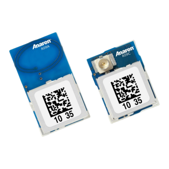
A1101R09x – User’s Manual Page 5 of 33 Release Date 05/08/12 1. Overview The A1101R09A and A1101R09C are surface mount modules – each with an integrated crystal, internal voltage regulator, matching circuitry and filtering. The A1101R09A has an integral antenna, whereas the A1101R09C utilizes an external antenna through a U.FL connector (see Table 2). -
Page 6: Features
Page 6 of 33 A1101R09x – User’s Manual Release Date 05/08/12 1.3. Features Features: Benefits Summary: Frequency range: 902-928 MHz Operating temperature -40 to +85C Ultra small package size 100% RF Tested in production A1101R09C : 9mm x 12mm x 2.5mm Common footprint for all family ... - Page 7 A1101R09x – User’s Manual Page 7 of 33 Release Date 05/08/12 To transmit, a frame of data is placed in the FIFO; this may include a destination address. A transmit command is given, which will transmit the data according to the initial setup of the registers.
- Page 8 Page 8 of 33 A1101R09x – User’s Manual Release Date 05/08/12 Figure 1 The functionality of the A1101R09A, using an integral antenna Figure 2 The functionality of the A1101R09C, using an external antenna. Arrow.com. Arrow.com. Arrow.com. Arrow.com. Arrow.com. Arrow.com. Arrow.com. Arrow.com.
-
Page 9: Typical Flow
A1101R09x – User’s Manual Page 9 of 33 Release Date 05/08/12 Figure 3 Transceiver IC block diagram. 1.4.1. Typical Flow After initial setup of registers for desired behavior, the normal operation flow diagram is shown in Figure 4. In applications of infrequent data transmissions, the transceiver would be in “sleep” mode to save power. - Page 10 Page 10 of 33 A1101R09x – User’s Manual Release Date 05/08/12 Medium access Figure 4 Transceiver state diagram Arrow.com. Arrow.com. Arrow.com. Arrow.com. Arrow.com. Arrow.com. Arrow.com. Arrow.com. Arrow.com. Arrow.com. Downloaded from Downloaded from Downloaded from Downloaded from Downloaded from Downloaded from Downloaded from Downloaded from Downloaded from...
-
Page 11: Applications
A1101R09x – User’s Manual Page 11 of 33 Release Date 05/08/12 1.5. Applications Ultra low-power wireless applications, operating in the 902-928 MHz ISM band. Wireless alarm and security systems Industrial monitoring and control Wireless sensor networks AMR –... - Page 12 Page 12 of 33 A1101R09x – User’s Manual Release Date 05/08/12 Table 1 Configuration Parameters Bit Fields Within Register Register Retained Address during Register Name (Hex) sleep IOCFG2 GDO2_INV GDO2_CFG IOCFG1 GDO_DS GDO1_INV GDO1_CFG IOCFG0 GDO0_INV GDO0_CFG GDO0_TEMP_SENSOR_ENABLE FIFOTHR Reserved ADC_RETENTION CLOSE_IN_RX FIFO_THR...
-
Page 13: Approvals And Usage
Table 2 Approved Antennas Item Part Number Manufacturer Type Gain Integral part of A1101R09A Anaren Integral Antenna 66089-0906 Anaren Monopole whip, 6mm lead 66089-0930 Anaren Monopole whip, 30mm lead 2.1.1.1. -
Page 14: End User Manual
Page 14 of 33 A1101R09x – User’s Manual Release Date 05/08/12 2.1.1.2. End User Manual The end user manual should include the following statement: This equipment has been tested and found to comply with the limits for a Class B digital device, pursuant to part 15 of the FCC Rules. -
Page 15: Canada (Industry Canada, Ic)
A1101R09x – User’s Manual Page 15 of 33 Release Date 05/08/12 2.1.2. Canada (Industry Canada, IC) The A1101R09A and A1101R09C modules have been certified for use in Canada under Industry Canada (IC) Radio Standards Specification (RSS) RSS-210 and RSS-Gen. From section 3.2 RSS-Gen, Issue 3, December 2010, Modular Approval for Category I Equipment or Category II Equipment: “Modular approval permits the installation of the same module in a host device or multiple host devices without the need to recertify the device. -
Page 16: Rf Exposure
Page 16 of 33 A1101R09x – User’s Manual Release Date 05/08/12 thereof). Each model shall be identified by a unique combination of a model number and a certification number, which are assigned as described below in this section. The label shall be securely affixed to a permanently attached part of the device, in a location where it is visible or easily accessible to the user, and shall not be readily detachable. -
Page 17: Potential Interference Sources
The user should use one of the register configurations listed below. Anaren provides register setting files for optimal performance and compliance for each of the data rates given in the following at www.anaren.com. Arrow.com. -
Page 18: Usa & Canada
Page 18 of 33 A1101R09x – User’s Manual Release Date 05/08/12 2.3.1. USA & Canada Within the USA and Canada, the modules have been approved for use as digitally modulated transmitters, for which they must have a minimum occupied bandwidth (6dB bandwidth) of 500kHz. -
Page 19: Electrical Characteristics
A1101R09x – User’s Manual Page 19 of 33 Release Date 05/08/12 3. Electrical Characteristics 3.1. Absolute Maximum Ratings Under no circumstances must the absolute maximum ratings given in Table 2 be violated. Stress exceeding one or more of the limiting values may cause permanent damage to the device. -
Page 20: Operating Conditions
The A1101R09A and A1101R09C radio modules share a common pin-out and foot print, that is also shared by Anaren modules using other frequencies -- thus enabling easy changeover from one to another, e.g. if changing the frequency, antenna scheme, or adaptive antenna tuning is desired. - Page 21 A1101R09x – User’s Manual Page 21 of 33 Release Date 05/08/12 Table 7 Pin Descriptions Pin # Pin Name Pin Type Description Internal GND connection used during testing, not recommended to connect to main GND. Internal RF output connection used during test. Connecting this pin to anything will require recertification for intentional radiators.
-
Page 22: Recommended Layout (Dimensions In Mm)
Page 22 of 33 A1101R09x – User’s Manual Release Date 05/08/12 3.4. Recommended Layout (dimensions in mm) Figure 6 Recommended PCB layout. Arrow.com. Arrow.com. Arrow.com. Arrow.com. Arrow.com. Arrow.com. Arrow.com. Arrow.com. Arrow.com. Arrow.com. Arrow.com. Arrow.com. Arrow.com. Arrow.com. Arrow.com. Arrow.com. Arrow.com. Arrow.com. Arrow.com. - Page 23 A1101R09x – User’s Manual Page 23 of 33 Release Date 05/08/12 Figure 8 Mounting the module along an edge Figure 7 Mounting the module in a corner Figure 9 Mounting the module along an edge with Figure 10 Mounting the module along an edge, with a overhang.
-
Page 24: Power Supply Considerations
Page 24 of 33 A1101R09x – User’s Manual Release Date 05/08/12 3.5. Power Supply Considerations Noise on the power supply line reduces the sensitivity of a receiver and modulates onto a transmitter’s signal, both of which causes a degradation of link quality and hence a reduction in range. -
Page 25: Mechanical And Process
A1101R09x – User’s Manual Page 25 of 33 Release Date 05/08/12 4. Mechanical and Process 4.1. Radio Module Details (dimensions in mm) 4.1.1. A1101R09A Figure 11 A1101R09A dimensions 4.1.2. A1101R09C Figure 12 A1101R09C dimensions Arrow.com. Arrow.com. Arrow.com. Arrow.com. Arrow.com. Arrow.com. Arrow.com. -
Page 26: Packaging Details (Dimensions In Mm)
Page 26 of 33 A1101R09x – User’s Manual Release Date 05/08/12 4.2. Packaging Details (dimensions in mm) AIR modules are available in Matrix Tray and Tape & Reel packaging for high-volume assembly. Details of packaging provided below: 4.2.1. Matrix Tray Packaging Figure 13 A1101R09A00GM Matrix Tray Packaging Detail (30/Tray) Figure 14 A1101R09C00GM Matrix Tray Packaging Detail (40/Tray) Arrow.com. -
Page 27: Tape-Reel Packaging
A1101R09x – User’s Manual Page 27 of 33 Release Date 05/08/12 4.2.2. Tape-Reel Packaging Figure 15 A1101R09A00GR Tape-Reel Packaging Detail (500/Reel) Figure 16 A1101R09C00GR Tape-Reel Packaging Detail (500/Reel) Arrow.com. Arrow.com. Arrow.com. Arrow.com. Arrow.com. Arrow.com. Arrow.com. Arrow.com. Arrow.com. Arrow.com. Arrow.com. Arrow.com. Arrow.com. -
Page 28: Soldering
Page 28 of 33 A1101R09x – User’s Manual Release Date 05/08/12 4.3. Soldering AIR Modules may be mounted either manually (for prototyping or low volume production), or automatically for high-volume production. A no-clean tin/silver/copper (SAC) solder is recommended, however lead based no-clean pastes may also be used. -
Page 29: Automated Mounting Procedure
A1101R09x – User’s Manual Page 29 of 33 Release Date 05/08/12 4.3.2. Automated Mounting Procedure The AIR Radio Module recommended solder reflow profile is based on IPC/JEDEC J-STD-020. Arrow.com. Arrow.com. Arrow.com. Arrow.com. Arrow.com. Arrow.com. Arrow.com. Arrow.com. Arrow.com. Arrow.com. Arrow.com. Arrow.com. Arrow.com. - Page 30 Page 30 of 33 A1101R09x – User’s Manual Release Date 05/08/12 Arrow.com. Arrow.com. Arrow.com. Arrow.com. Arrow.com. Arrow.com. Arrow.com. Arrow.com. Arrow.com. Arrow.com. Arrow.com. Arrow.com. Arrow.com. Arrow.com. Arrow.com. Arrow.com. Arrow.com. Arrow.com. Arrow.com. Arrow.com. Arrow.com. Arrow.com. Arrow.com. Arrow.com. Arrow.com. Arrow.com. Arrow.com. Arrow.com. Arrow.com. Arrow.com.
- Page 31 A1101R09x – User’s Manual Page 31 of 33 Release Date 05/08/12 DOCUMENT HISTORY Date Author Change Note No./Notes 07/17/10 Richardson Initial Draft 08/23/10 Richardson Initial Release 11/19/10 Richardson Formatting applied – no content change 02/10/11 Richardson Corrected typographic error 07/06/11 Richardson Corrected typographic errors / added process section...
- Page 32 THIS PAGE INTENTIONALLY LEFT BLANK Arrow.com. Arrow.com. Arrow.com. Arrow.com. Arrow.com. Arrow.com. Arrow.com. Arrow.com. Arrow.com. Arrow.com. Arrow.com. Arrow.com. Arrow.com. Arrow.com. Arrow.com. Arrow.com. Arrow.com. Arrow.com. Arrow.com. Arrow.com. Arrow.com. Arrow.com. Arrow.com. Arrow.com. Arrow.com. Arrow.com. Arrow.com. Arrow.com. Arrow.com. Arrow.com. Arrow.com. Arrow.com. Downloaded from Downloaded from Downloaded from Downloaded from Downloaded from...
- Page 33 For a full list of our franchised distributors, please visit our website: http://www.anaren.com/air/ Anaren Microwave, Inc. Anaren Microwave (Europe), Inc. Anaren Communication Suzhou Co. Ltd. 6635 Kirkville Road 12 Somerset House, Suite 16 & 17 No. 5 Chun Hui Road...
Need help?
Do you have a question about the A1101R09 Series and is the answer not in the manual?
Questions and answers