
Related Manuals for Bailey infi 90 E96-202

Summary of Contents for Bailey infi 90 E96-202
- Page 1 E96-202 ® ® Multi-Function Processor Module (IMMFP02) Process Control and Automation Solutions from Elsag Bailey Group...
- Page 2 The information contained in this document is subject to change without notice. Elsag Bailey, its affiliates, employees, and agents, and the authors and contributors to this publication specif- ically disclaim all liabilities and warranties, express and implied (including warranties of merchantability and...
- Page 3 Preface The IMMFP02 Multi-Function Processor Module is a powerful stand-alone controller for use in complex control applications. It has the processing speeds and storage capabilities necessary for advanced control applications. The IMMFP02 module is a user-configurable device that receives process input and out- put through a variety of analog and digital I/O modules.
- Page 4 ® List of Effective Pages Total number of pages in this instruction is 72, consisting of the following: Page No. Change Date Preface Original List of Effective Pages Original iii through viii Original 1-1 through 1-6 Original 2-1 through 2-4 Original 3-1 through 3-10 Original...
- Page 5 Safety Summary GENERAL Equipment Environment WARNINGS All components, whether in transportation, operation or storage, must be in a noncorrosive environment. Electrical Shock Hazard During Maintenance Disconnect power or take precautions to insure that contact with energized parts is avoided when servicing. Special Handling This module uses electrostatic sensitive devices (ESD).
- Page 6 ® Sommaire de Sécurité AVERTISSEMENT Environment de l'Equipement D'ORDRE Nes pas soumettre les composantes a une atmosphere corrosive GENERAL lors du transport, de l'entreposage ou de l'utilisation. Risques de Chocs Electriques lor de l'Entretien S'assurer de debrancher l'alimentation ou de prende les precau- tions necessaires a eviter tout contact avec des composants sours tension lors de l'entretien.
- Page 7 Safety Summary GENERAL Equipment Environment WARNINGS All components, whether in transportation, operation or storage, must be in a noncorrosive environment. Electrical Shock Hazard During Maintenance Disconnect power or take precautions to insure that contact with energized parts is avoided when servicing. Special Handling This module uses electrostatic sensitive devices (ESD).
- Page 8 ® Sommaire de Sécurité AVERTISSEMENT Environment de l'Equipement D'ORDRE Nes pas soumettre les composantes a une atmosphere corrosive GENERAL lors du transport, de l'entreposage ou de l'utilisation. Risques de Chocs Electriques lor de l'Entretien S'assurer de debrancher l'alimentation ou de prende les precau- tions necessaires a eviter tout contact avec des composants sours tension lors de l'entretien.
-
Page 9: Table Of Contents
Table of Contents Page SECTION 1 - INTRODUCTION ....................1-1 OVERVIEW ........................1-1 INTENDED USER ......................1-1 HARDWARE DESCRIPTION..................1-1 Faceplate .......................1-2 Circuit Board ......................1-3 HARDWARE APPLICATION...................1-3 FEATURES........................1-3 INSTRUCTION CONTENT .....................1-3 HOW TO USE THIS MANUAL ..................1-4 REFERENCE DOCUMENTS..................1-4 NOMENCLATURE ......................1-4 GLOSSARY OF TERMS AND ABBREVIATIONS .............1-5 SPECIFICATIONS ......................1-6 SECTION 2 - DESCRIPTION AND OPERATION................2-1 INTRODUCTION......................2-1... - Page 10 ® Table of Contents (continued) Page SECTION 4 - OPERATING PROCEDURES (continued) MODES OF OPERATION ....................4-4 Configure Mode ..................... 4-4 Execute Mode ......................4-4 Error Mode ......................4-4 SECTION 5 - TROUBLESHOOTING...................5-1 INTRODUCTION ......................5-1 CARD EDGE CONNECTORS ..................5-5 DIAGNOSTICS ......................
- Page 11 List of Figures Title Page 1-1. Example IMMFP02 Module Applications..............1-2 2-1. IMMFP02 Module Functional Block Diagram ............2-1 3-1. IMMFP02 Module Layout ..................3-3 3-2. Controlway Cable Installation ................3-8 4-1. IMMFP02 Front Panel LEDs and Controls ..............4-2 5-1. IMMFP02 Troubleshooting Flowchart (Serial Port) ..........5-4 5-2.
- Page 12 ® List of Tables (continued) Title Page 5-7. IMDSM05 Jumper Settings for IMMFP02 Tests ............5-7 5-8. Diagnostic Tests ....................5-8 5-9. IMMFP02 Module Status Report ................5-11 5-10. Field Descriptions of the IMMFP02 Module Status Report ........5-11 6-1. Preventive Maintenance Schedule ................
-
Page 13: Section 1 - Introduction
(especially function codes) would help when con- figuring the MFP module. HARDWARE DESCRIPTION The multi-function processor module consists of a faceplate and circuit board. ® INFI 90 is a registered trademark of Elsag Bailey Process Automation. OVERVIEW I-E96-202B 1 - 1... -
Page 14: Faceplate
INTRODUCTION ® INFI-NET OR PLANT LOOP PROCESS CONTROL INNIS01 INNPM01 UNIT INTERFACE CONTROLWAY SECONDARY PRIMARY I/O EXPANDER BUS MODULE MODULE MODULE IMCIS02 NTMP01 UP TO 64 MODULES RS-232-C RS-485 RS-485 NTCS04 RS-485 IISAC01 IISAC01 IISAC01 TP36096B Figure 1-1. Example IMMFP02 Module Applications Faceplate The MFP faceplate measures 35.56 millimeters wide by 177.80 millimeters high (1.4 inches wide by seven inches high). -
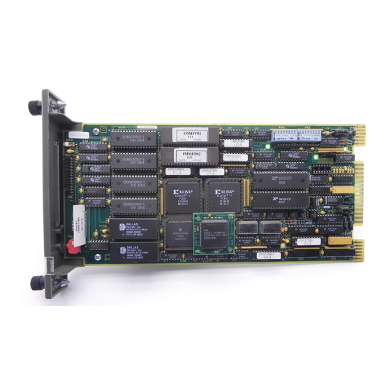
Page 15: Circuit Board
(RAM), read only memory (ROM), a microproces- sor running at 16 megahertz, direct memory access (DMA) cir- cuits, Bailey custom bus circuits and various support circuitry. The board attaches to the faceplate with two screws. The module assembly occupies one slot in a module mounting unit. -
Page 16: How To Use This Manual
INTRODUCTION ® Support Services A list of the replacement parts and an explanation of the war- ranty policy are contained in this section. Appendices These appendices provide quick reference information for the hardware configuration of the IMMFP02 module and associ- ated termination units and modules and step by step instruc- tions for performing on-line configuration. -
Page 17: Glossary Of Terms And Abbreviations
A point of interconnection to a network. Process control unit. A node on the plantwide communication network containing control and I/O modules. ® Network 90 is a registered trademark of Elsag Bailey Process Automation. GLOSSARY OF TERMS AND ABBREVIATIONS I-E96-202B... -
Page 18: Specifications
INTRODUCTION ® Table 1-3. Glossary of Terms and Abbreviations (continued) Term Description Analog control station. Termination Module Provides input/output connection between plant equipment and the INFI 90/ Net- work 90 modules. Termination Unit Provides input/output connection between plant equipment and the INFI 90/ Net- work 90 modules. -
Page 19: Section 2 - Description And Operation
SECTION 2 - DESCRIPTION AND OPERATION INTRODUCTION The IMMFP02 Multi-Function Processor Module functions like a series of functional blocks working together. To explain how the MFP module works, this section shows MFP module func- tionality as a block diagram (see Figure 2-1) and then explains each block in the following text. -
Page 20: Clock And Timer
I/O data between control and I/O modules. It supports up to 64 low power I/O modules. The bus uses a protocol designed by Bailey Controls Company to ensure data integrity. The bus bandwidth is 500 kilobytes per second, however actual throughput is about 100 kilobytes per second. -
Page 21: Serial Channels
32 connections. The Controlway interface is provided by a custom Bailey Controls integrated circuit that links the MFP module to the Controlway. It has full DMA capabilities (allowing for quicker operation), and two redundant, independent communication channels. -
Page 22: Redundancy Link
DESCRIPTION AND OPERATION ® There are two separate communication paths on the module mounting unit backplane circuit allotted for Controlway com- munications. Data is transmitted over both channels simulta- neously and received in separate receivers where it is checked for integrity. In this way, the Controlway minimizes the chances that a failure on a circuit board, or the backplane will cause loss of module communication. -
Page 23: Section 3 - Installation
SPECIAL HANDLING Observe these steps when handling electronic circuitry: NOTE: Always use Bailey Controls field static kit (part number 1948385_1 - consisting of two wrist straps, ground cord assembly, alligator clip, and static dissipating work surface) when working with the modules. -
Page 24: Unpacking And Inspection
UNPACKING AND INSPECTION 1. Examine the hardware immediately for shipping damage. 2. Notify the nearest Bailey Controls sales office of any such damage. 3. File a claim for any damage with the transportation com- pany that handled the shipment. -
Page 25: Immfp02 Module Layout
INSTALLATION -3 0 V D C S Y S T E M (D E F A U L T ) C O N T R O L W A Y 1 2 3 4 5 6 7 8 1 2 3 4 5 6 7 8 S W 3 S W 4 M A C H IN E F A U L T T IM E R... -
Page 26: Dipswitch Sw4 Settings
INSTALLATION ® Table 3-2. Example IMMFP02 Module Address Settings Dipswitch Position (Binary Value) Address Example (16) User Setting NOTE: 0 = CLOSED or ON, 1 = OPEN or OFF. Dipswitch SW4 Settings Dipswitch SW4 enables the selection of a variety of module options. -
Page 27: Special Operations
It is applica- ble only to INFI-NET systems. NOTE: 0 = CLOSED or ON, 1 = OPEN or OFF. ® Registered trademark of Elsag Bailey Process Automation. SETUP AND PHYSICAL INSTALLATION I-E96-202B... -
Page 28: Jumpers J1 Through J5
INSTALLATION ® To execute special operations: 1. Set pole 1 of dipswitch SW4 to the open (off) position. 2. Set poles 2 through 8 for the desired operation in accor- dance with Table 3-4. 3. Insert the module into its assigned slot in the module mounting unit. -
Page 29: Preparing The Module Mounting Unit
NOTE: Two unlabeled jumper pins are located at the front of the MFP circuit board. These are for Bailey Controls development per- sonnel only. They are used to disable the machine fault timer circuit. If this function is disabled (jumper pins connected) and a problem develops in the MFP module, the module will not halt which may result in configuration corruption and unpredictable module outputs. -
Page 30: Controlway Cable
INSTALLATION ® Controlway Cable Install the Controlway or module bus cable in INFI 90 module mounting units as follows: 1. Attach one end of the Controlway or module bus cable (twisted 3-wire) to the bottom three tabs on the lower left of the module mounting unit backplane (facing from behind). -
Page 31: Nimp01 Or Nimp02 Termination Module Installation
INSTALLATION 2. Install the termination unit on the termination unit panel and secure into place. 3. Connect the hooded end of the NKTU01 or NKTU11 cable to the rear of the module mounting unit slot assigned to the MFP module. 4. - Page 32 INSTALLATION ® 2. Check for -30 VDC with respect to system common at the -30 VDC faston. 3. If -30 VDC is present, set jumper J5 and dipswitch SW3 to the appropriate positions. Before installing the MFP module: 1. Check all module dipswitch and jumper settings (normal and special operation) 2.
-
Page 33: Section 4 - Operating Procedures
SECTION 4 - OPERATING PROCEDURES INTRODUCTION This section explains what happens to the IMMFP02 Multi-Function Processor (MFP) Module during start-up, the LED indicators and what they mean, how to stop or reset the module, and the three modes of operation. STARTUP When power is applied to the MFP module, the module does an internal hardware check, checks its configuration and builds... -
Page 34: Front Panel Leds One Through Eight
OPERATING PROCEDURES ® IMMFP02 RED/GREEN STATUS LED LEDs 1-8 STOP/RESET SWITCH TP50347A Figure 4-1. IMMFP02 Front Panel LEDs and Controls Front Panel LEDs One through Eight These LEDs indicate MFP module error codes. In redundant configurations, these LEDs also designate the primary MFP module and the secondary MFP module. -
Page 35: Stop/Reset Switch
OPERATING PROCEDURES Solid Green The MFP module is in execute mode. Flashing Green The MFP module is in execute mode but there is an NVRAM checksum error, or the MFP module is in configure or error mode. Solid Red The MFP module diagnostics have detected a hardware failure, configuration problem, etc. -
Page 36: Modes Of Operation
OPERATING PROCEDURES ® Recover from a module time-out or operator-initiated stop. • NOTE: Pressing and holding the stop/reset switch provides no addi- tional functionality over pressing and releasing the switch. To stop the module, press and release the stop/reset switch. To reset the module, press the stop/reset switch a second time. -
Page 37: Section 5 - Troubleshooting
NVRAM memory opened Initialize the NVRAM memory. If the for write operation error recurs, replace the MFP module. If error recurs call Bailey field service. 0 0 0 0 1 1 0 1 Redundancy link Check the cable connection between communication error primary and secondary MFP modules. - Page 38 Section 3 for details. different 0 0 0 1 0 0 1 1 ROM memory checksum Call Bailey field service. error 0 0 0 1 0 1 0 0 MFP set for INFI-NET, Initialize the MFP module. when actually in a Plant...
-
Page 39: Other Immfp02 Module Led Conditions
0 0 1 1 0 0 0 1 Memory or CPU fault Replace the MFP module. If error recurs, call Bailey field service. 0 0 1 1 0 0 1 0 Address or bus error Reset MFP module. If error recurs, call Bailey field service. -
Page 40: Immfp02 Troubleshooting Flowchart (Serial Port)
TROUBLESHOOTING ® ST AR T RS-232-C LINE ERRORS ON D O N E MFP LEDs (CODE 15)? Y ES + 2 4 V D C R E F E R T O T M P /IM P O P E N O N C O NN E C TE D TO IN S T R U C T IO N S T O T U /T M ? -
Page 41: Card Edge Connectors
TROUBLESHOOTING START STATUS STATUS LED STATUS LED STATUS LED LED OFF? RED? ORANGE? GREEN? TURN ON POWER ON? ERROR CODE POWER DONE REMOVE MACHINE DISPLAYED? FAULT TIMER JUMPER FROM MFP MODULE PERFORM SEAT MFP CORRECTIVE MODULE SEATED MODULE IN MMU ACTION APPLICABLE IN MMU? BACKPLANE... -
Page 42: Diagnostics
TROUBLESHOOTING ® Table 5-4. IMMFP02 Connector P2 Pin Assignments Signal Signal Data Bit 1 Data Bit 0 Data Bit 3 Data Bit 2 Data Bit 5 Data Bit 4 Data Bit 7 Data Bit 6 Bus Clock Synchronization Reserved Reserved NOTE: All data bits are true low. -
Page 43: Dipswitch Selection
TROUBLESHOOTING The typical procedure is to select a diagnostic test to execute, set the module dipswitches accordingly, reset the module, and observe the results on LEDs one through eight. The selected test executes repeatedly until the MFP module is reset and another test is selected. -
Page 44: Diagnostic Dipswitch Settings
TROUBLESHOOTING ® DIPSWITCH MODULE ADDRESS BUS MODE (OFF = MODULE BUS, ON = CONTROLWAY) UNUSED DIAGNOSTIC MODE (OFF = ENABLED, ON = DISABLED) DIPSWITCH TEST ID HALT ON ERROR (ON = DISABLED, OFF = ENABLED) OFF = PASS/FAIL DISPLAY, ON = TEST NUMBER DISPLAY TP21168A Figure 5-3. -
Page 45: Led Display
TROUBLESHOOTING Table 5-8. Diagnostic Tests (continued) Test Name Test ID Description I/O Expander Bus Stall Sets a latch enabling a level 7 interrupt to occur. Module Bus/Controlway Sends series of bytes to Controlway verifying timing and transfer status. Timer IRQ Initializes DUART timer for 1-msec interrupts and then waits for it to time-out. -
Page 46: Module Status Summary
TROUBLESHOOTING ® LED 1 LED 2 PASS COUNT LED 3 TEST NUMBER LED 4 LED 5 LED 6 FAILURE COUNT NOT USED LED 7 TEST NUMBER LED 8 MODE FAIL TP50335B Figure 5-4. LEDs - Pass/Fail Resetting the MFP module causes all eight LEDs (LEDs one through eight) to illuminate. -
Page 47: Nomenclature
TROUBLESHOOTING Table 5-9. IMMFP02 Module Status Report Byte MODE MODULE TYPE Bytes 3-5 combine to define other errors. Extended module type = 24 8 - 13 Unused Nomenclature (decimal digit) Firmware revision level (ASCII letter) Firmware revision level (ASCII digit) NOTE: 1. - Page 48 TROUBLESHOOTING ® Table 5-10. Field Descriptions of the IMMFP02 Module Status Report (continued) Field Value Description Bytes 3 through 5 (continued) Analog input reference error: 1 V reference 5 V reference <X> <Y> Missing I/O module: XY = block no. <X>...
-
Page 49: Section 6 - Maintenance
éclaboussures qui risquent d'atteindre les yeux. The reliability of any stand-alone product or control system is affected by the maintenance of the equipment. Bailey Controls Company recommends that all equipment users practice a pre- ventive maintenance program that will keep the equipment operating at an optimum level. -
Page 50: Equipment And Tools Required
MAINTENANCE ® Table 6-1. Preventive Maintenance Schedule Task Frequency Check cabinet air filters. Clean or replace them as necessary. Check the air filter more fre- 3 months quently in excessively dirty environments. Check cabinet and MFP module for dust. Clean as necessary using an antistatic vacuum. Check all MFP module signal, power and ground connections within the cabinet. -
Page 51: General Cleaning And Washing
MAINTENANCE GENERAL CLEANING AND WASHING If the printed circuit board needs minor cleaning, remove dust and residue from the printed circuit board surface using clean, dry, filtered compressed air or an antistatic field service vac- uum cleaner. Another method of washing the printed circuit board is: 1. - Page 52 MAINTENANCE ® direction to tighten only. If the connection is loose, it will be tightened. If the connection is tight, the tightening action will verify that it is secure. There must not be any motion done to loosen the connection. NOTE: Power to the cabinet must be off while performing this pre- ventive maintenance task.
-
Page 53: Section 7 - Repair/Replacement Procedures
SECTION 7 - REPAIR/REPLACEMENT PROCEDURES INTRODUCTION Repair procedures are limited to module replacement. If the IMMFP02 Multi-Function Processor Module fails, remove and replace it with another. Verify that firmware revision levels match and that the replacement module switch and jumper settings are the same as those of the failed module. -
Page 54: Section 8 - Support Services
SECTION 8 - SUPPORT SERVICES INTRODUCTION Bailey Controls is ready to help in the use and repair of its products. Contact the nearest sales office to make requests for sales, applications, installation, repair, overhaul and mainte- nance contract services. REPLACEMENT PARTS AND ORDERING INFORMATION When making repairs, order replacement parts from a Bailey sales office. -
Page 55: Appendix A - Quick Reference Material
APPENDIX A - QUICK REFERENCE MATERIAL INTRODUCTION This appendix provides quick reference information to aid in the hardware configuration of the IMMFP02 Multi-Function Processor Module. Table show the settings for dipswitches SW3 and SW4. Table shows the jumper set- tings for jumper J5. Table is an abbreviated error code list- ings. -
Page 56: Immfp02 Module Error Codes
QUICK REFERENCE MATERIAL ® Table A-2. IMMFP02 Dipswitch SW4 Settings (continued) Pole Setting Function Primary MFP module. Redundant MFP module. NOTES: 0 = CLOSED or ON, 1 = OPEN or OFF. 1. Disabling the checksum routine is sometimes done by development personnel and should never be done for normal operation. - Page 57 QUICK REFERENCE MATERIAL Table A-4. IMMFP02 Module Error Codes (continued) Code Condition 8 7 6 5 4 3 2 1 0 0 0 1 0 0 1 0 Primary and secondary module addresses are different 0 0 0 1 0 0 1 1 ROM memory checksum error 0 0 0 1 0 1 0 0 MFP set for INFI-NET, when actu-...
-
Page 58: Other Immfp02 Module Led Conditions
QUICK REFERENCE MATERIAL ® Table A-5. Other IMMFP02 Module LED Conditions Condition Problem Status No power, improper module seating, or defective module. Module not properly seated or module defective. GREEN None - normal condition. No power, improper module seating, or defective module. -
Page 59: Appendix B - On-Line Configuration
This appendix provides a step by step procedure for performing on-line configuration. Use the configuration and tuning mod- ule, configuration tuning terminal, operator interface station console, management command system console, or engineer- ing workstation with appropriate Bailey Controls Company configuration software to accomplish on-line configuration. INTRODUCTION I-E96-202B... - Page 60 PCU status display selected from the system status display. With an engineering work station using the Bailey Controls Company CAD/TEXT software package, select the problem report option. Please note that this option does not continuously poll for module status.
-
Page 61: Backup Cycle
ON-LINE CONFIGURATION Backup Cycle The step numbers in this cycle correspond to the status of Fig- ure B-1. Table B-2. Backup Cycle Primary Backup Procedure 1. Place the backup MFP module into execute mode. This saves a copy of the 00xx0x0x 10xx0x0x primary modules current configuration and enables it to be easily restored if... -
Page 62: Primary Cycle
ON-LINE CONFIGURATION ® Table B-2. Backup Cycle (continued) Primary Backup Procedure 5. When the checkpoint data for the old configuration is received from the pri- 01xx0x0x 10xx1x0x mary MFP module, the reconfigured backup MFP module can assume the role of the primary MFP module if a failure is detected in the old configuration (see Step 9). -
Page 63: Backup Mfp Module Operating Cycle
ON-LINE CONFIGURATION BACKUP BACKUP INITIALIZE EEROM BUSCLK RESET (NO CHANGE) PRIMARY BACKUP BACKUP CHECKPOINT DATA CONFIGURATION IS COMPLETE IS COPIED TO THE BACKUP BUSCLK PRIMARY BACKUP RESET (CONFIGURATION NOT COPIED) RESET (CHANGES MADE) BUSCLK BUSCLK REQUEST CHECKPOINT BACKUP BACKUP BACKUP SHUTDOWN DATA IS OF PRIMARY... -
Page 64: Primary Mfp Module Operating Cycle
ON-LINE CONFIGURATION ® Table B-3. Primary Cycle (continued) Primary Backup Procedure 4. Resetting the primary MFP module (n+1), currently acting as the hot backup, 00xx0x0x 00xx1x0x directs it to get a copy of the new configuration (Step 9 of the backup cycle). 5. -
Page 65: Dte Jumper Configuration For Ntmp01 Termination Unit
APPENDIX C - NTMP01 TERMINATION UNIT CONFIGURATION INTRODUCTION The IMMFP02 Multi-Function Processor Module can use the NTMP01 termination unit for termination. Jumpers on the NTMP01 unit configure the two RS-232-C ports for data termi- nal equipment (DTE) or data communication equipment (DCE). One of the RS-232-C ports can be configured as an RS-485 port. -
Page 66: Appendix C - Ntmp01 Termination Unit Configuration
NTMP01 TERMINATION UNIT CONFIGURATION ® J1 AND J2 DB25-3 TXD-A RXD-A DB25-2 RTS-A DB25-4 DB25-5 CTS-A TP25052B Figure C-2. DCE Jumper Configuration for NTMP01 Termination Unit J1 AND J2 DB25-3 TXD-A RXD-A DB25-2 RTS-A DB25-4 DB25-5 CTS-A TP22115A Figure C-3. NTMP01 Nonhandshake Jumper Configuration INTRODUCTION C - 2... -
Page 67: Ntmp01 Jumpers J3 Through J10 Configuration
NTMP01 TERMINATION UNIT CONFIGURATION J1 AND J2 TXD-A DB25-3 RXD-A DB25-2 RTS-A DB25-4 CTS-A DB25-5 TP22116A Figure C-4. NTMP01 Loopback Jumper Configuration +12 V J6 AND J8 DB25-6 J5 AND J9 DB25-8 J7 AND J10 DB25-20 J4 AND J3 PROT-GND DB25-1 DB25-7 NOTE: JUMPERS J3, J8, J9 AND J10 RELATE TO... -
Page 68: Ntmp01 Jumpers J14 Through J17 Configuration
NTMP01 TERMINATION UNIT CONFIGURATION ® DIGIN 1 (+) DIGIN 1 (+) CTSB (+) CTSB (+) DIGIN 1 (-) DIGIN 1 (-) CTSB (-) CTSB (-) HANDSHAKE DIGITAL I/O TP25216B Figure C-6. NTMP01 Jumpers J14 through J17 Configuration STATION MFP2 COM. B ACTIVE NTMP01 MFP2... -
Page 69: Ntmp01 Cable Connections For Redundant Mfp Modules
NTMP01 TERMINATION UNIT CONFIGURATION TO NTCS04 (CABLE REQUIRED ONLY IF STATIONS ARE USED) NKTU01 NKSE01 NKSE01 NKTU11 NKSE11 NKSE11 IMMFP0_ RS-232-C PORTS NKTU01 NTMP01 NKTU11 NOTE: P5 AND P7 CANNOT BE IMMFP0_ USED AT THE SAME TIME. RS-485 PORT REDUNDANT IMMFP0_s WITH OR WITHOUT STATIONS (NDCS03/IISAC01 AND/OR NDIS01) AND WITH RS-232-C PORTS TP36172A Figure C-8. -
Page 70: Appendix D - Nimp01/Nimp02 Termination Module Configuration
P7 is used instead of P5. NOTES: RS-232-C port connections on the IMP module are through DB-9 connectors. Use Bailey Controls cable NKMR02 to connect a standard piece of equipment (computer or printer with a DB-25 con- nector) to the IMP module. -
Page 71: Dte Jumper Configuration For Nimp01 Termination Module
NIMP01/NIMP02 TERMINATION MODULE CONFIGURATION ® J1 AND J2 TXD-A DB9-2 RXD-A DB9-3 RTS-A DB9-7 CTS-A DB9-8 TP22148A Figure D-1. DTE Jumper Configuration for NIMP01 Termination Module J1 AND J2 DB9-2 TXD-A RXD-A DB9-3 RTS-A DB9-7 DB9-8 CTS-A TP22147A Figure D-2. DCE Jumper Configuration for NIMP01 Termination Module INTRODUCTION D - 2... -
Page 72: D-3. Nimp01 Nonhandshake Jumper Configuration
NIMP01/NIMP02 TERMINATION MODULE CONFIGURATION J1 AND J2 DB9-2 TXD-A RXD-A DB9-3 RTS-A DB9-7 DB9-8 CTS-A TP22149A Figure D-3. NIMP01 Nonhandshake Jumper Configuration J1 AND J2 TXD-A DB9-2 RXD-A DB9-3 RTS-A DB9-7 CTS-A DB9-8 TP22150A Figure D-4. NIMP01 Loopback Jumper Configuration +12 V J19 AND J20 DB9-8... -
Page 73: Nimp01 Jumpers J14 Through J17 Configuration
NIMP01/NIMP02 TERMINATION MODULE CONFIGURATION ® DIGIN 1 (+) DIGIN 1 (+) CTSB (+) CTSB (+) DIGIN 1 (-) DIGIN 1 (-) CTSB (-) CTSB (-) HANDSHAKE DIGITAL I/O TP25216B Figure D-6. NIMP01 Jumpers J14 through J17 Configuration CHASSIS GROUND SYSTEM COMMON +24 VDC TERMINAL PORT (RS-232-C) -
Page 74: Nimp01 And Nimp02 Cable Connections For Redundant Mfp Modules
NIMP01/NIMP02 TERMINATION MODULE CONFIGURATION RS-232-C PORTS NKTU02 NKTU12 IMMFP0_ SERIAL LINK NIMP01 FOR STATIONS LINK B LINK A IF REQUIRED (TO NICS01) RS-485 PORT 6634408A2 NOTE: P5 AND P7 CANNOT BE USED AT THE SAME TIME. RS-232-C PORT NKTU02 NKTU12 IMMFP0_ NIMP02 SERIAL LINK... - Page 75 Index Abbreviations.............. 1-5 Error codes ............5-1, A-2 Associated documents ..........1-4 Error mode ..............4-4 Example applications ........1-2, C-5, D-5 Execute mode .............4-4 Cables Controlway............3-8 Module bus ............3-8 Faceplate .............1-2, 4-2 Termination module ....... 1-4, 3-9, D-5 Function blocks ............1-1, 4-4 Termination unit ........
- Page 76 ® Index (continued) Latching screws ............3-10 Redundancy ............... 2-4 LEDs References ..............1-4 1 through 8 ........1-2, 4-2, 5-10, A-2 RS-232-C..........1-6, 5-8, C-5, D-5 Startup sequence ..........4-1 RS-485 ............1-6, C-5, D-5 Status .............1-2, 4-2 Serial port troubleshooting.......... 5-4 Maintenance schedule ..........6-1 Software configuration..........
- Page 77 For prompt, personal attention to your instrumentation and control needs or a full listing of Bailey representatives in principal cities around the world, contact the Bailey location nearest you. Australia Japan United Kingdom Elsag Bailey Pty. Limited Bailey Japan Company, Ltd.
Need help?
Do you have a question about the infi 90 E96-202 and is the answer not in the manual?
Questions and answers