Sign In
Upload
Manuals
Brands
Bailey Manuals
Computer Hardware
IMMFP02
User Manuals: Bailey IMMFP02 Industrial Control System
Manuals and User Guides for Bailey IMMFP02 Industrial Control System. We have
1
Bailey IMMFP02 Industrial Control System manual available for free PDF download: Instructions Manual
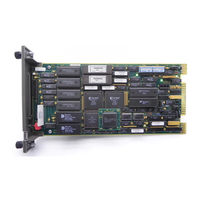
Bailey IMMFP02 Instructions Manual (77 pages)
Multi-Function Processor Module
Brand:
Bailey
| Category:
Computer Hardware
| Size: 1 MB
Table of Contents
Table of Contents
9
Section 1 - Introduction
13
Overview
13
Intended User
13
Hardware Description
13
Faceplate
14
Example IMMFP02 Module Applications
14
Circuit Board
15
Hardware Application
15
Features
15
Instruction Content
15
How to Use this Manual
16
Reference Documents
16
Nomenclature
16
Glossary of Terms and Abbreviations
17
Specifications
18
Section 2 - Description and Operation
19
Introduction
19
Microprocessor
19
IMMFP02 Module Functional Block Diagram
19
Clock and Timer
20
Memory
20
I/O Expander Bus
20
I/O Section
20
Serial Channels
21
Dma Section
21
Controlway
21
Redundancy Link
22
Station Link
22
Section 3 - Installation
23
Introduction
23
Special Handling
23
Unpacking and Inspection
24
Setup and Physical Installation
24
Dipswitch SW3 Settings
24
IMMFP02 Module Layout
25
IMMFP02 Dipswitch SW3 Settings
25
Dipswitch SW4 Settings
26
Example IMMFP02 Module Address Settings
26
IMMFP02 Dipswitch SW4 Normal Operation Settings
26
Special Operations
27
IMMFP02 Dipswitch SW4 Special Operation Settings
27
Jumpers J1 through J5
28
Preparing the Module Mounting Unit
29
Dipshunts
29
IMMFP02 Jumpers J1 through J5 Settings
29
Controlway Cable
30
Installing the Termination Unit or Module
30
NTMP01 Termination Unit Installation
30
Controlway Cable Installation
30
NIMP01 or NIMP02 Termination Module Installation
31
Installing the Module
31
Section 4 - Operating Procedures
33
Introduction
33
Startup
33
Led Indicators
33
Front Panel Leds One through Eight
34
Red/Green Status LED
34
IMMFP02 Front Panel Leds and Controls
34
Stop/Reset Switch
35
SECTION 4 - OPERATING PROCEDURES (Continued)
35
Modes of Operation
36
Configure Mode
36
Execute Mode
36
Error Mode
36
Section 5 - Troubleshooting
37
Introduction
37
IMMFP02 Module Error Codes
37
Other IMMFP02 Module LED Conditions
39
IMMFP02 Troubleshooting Flowchart (Serial Port)
40
Card Edge Connectors
41
IMMFP02 Troubleshooting Flowchart (Status LED)
41
IMMFP02 Connector P1 Pin Assignments
41
Diagnostics
42
Overview
42
IMMFP02 Connector P2 Pin Assignments
42
IMMFP02 Connector P3 Pin Assignments
42
Dipswitch Selection
43
IMDSM05 Switch Settings for IMMFP02 Tests
43
IMDSM05 Jumper Settings for IMMFP02 Tests
43
Diagnostic Dipswitch Settings
44
Diagnostic Tests
44
LED Display
45
Module Status Summary
46
Leds - Pass/Fail
46
Nomenclature
47
IMMFP02 Module Status Report
47
Section 6 - Maintenance
49
Introduction
49
Preventive Maintenance Schedule
49
Equipment and Tools Required
50
Preventive Maintenance Procedures
50
Printed Circuit Board Cleaning
50
Preventive Maintenance Schedule
50
General Cleaning and Washing
51
Edge Connector Cleaning
51
Checking Connections
51
Section 7 - Repair/Replacement Procedures
53
Introduction
53
Module Replacement Procedure
53
Termination Unit or Module Replacement Procedures
53
Section 8 - Support Services
54
Introduction
54
Replacement Parts and Ordering Information
54
Training
54
Technical Documentation
54
Spare Parts List
54
Appendix A - Quick Reference Material
55
Introduction
55
IMMFP02 Dipswitch SW3 Settings
55
IMMFP02 Dipswitch SW4 Settings
55
IMMFP02 Module Error Codes
56
Other IMMFP02 Module LED Conditions
58
Appendix B - On-Line Configuration
59
Introduction
59
Setup
59
Operation
59
Backup Cycle
61
Primary Cycle
62
Backup MFP Module Operating Cycle
63
Primary Cycle
63
Primary MFP Module Operating Cycle
64
DTE Jumper Configuration for NTMP01 Termination Unit
65
Appendix C - Ntmp01 Termination Unit Configuration
66
Introduction
66
DCE Jumper Configuration for NTMP01 Termination Unit
66
NTMP01 Jumpers J3 through J10 Configuration
67
NTMP01 Jumpers J14 through J17 Configuration
68
NTMP01 Cable Connections for Redundant MFP Modules
69
NTMP01 Cable Connections for a Single MFP Module
69
Appendix D - Nimp01/Nimp02 Termination Module Configuration
70
Introduction
70
DTE Jumper Configuration for NIMP01 Termination Module
71
DCE Jumper Configuration for NIMP01 Termination Module
71
D-3. NIMP01 Nonhandshake Jumper Configuration
72
D-4. NIMP01 Loopback Jumper Configuration
72
NIMP01 Jumpers J14 through J17 Configuration
73
NIMP01 and NIMP02 Cable Connections for Redundant MFP Modules
74
Advertisement
Advertisement
Related Products
Bailey infi90 IMMFP11
Bailey infi90 IMMFP03
Bailey infi90 IMMFP03B
Bailey IMFCS01
Bailey IMFEC11
Bailey IMFEC12
Bailey IMASO11
Bailey IMCIS12
Bailey IMQRS12
Bailey IMCIS02
Bailey Categories
Control Unit
Motorhomes
Lighting Equipment
Recording Equipment
Controller
More Bailey Manuals
Login
Sign In
OR
Sign in with Facebook
Sign in with Google
Upload manual
Upload from disk
Upload from URL