Table of Contents
Advertisement
Quick Links
Advertisement
Table of Contents

Related Manuals for Beckhoff CX2500-0070


Summary of Contents for Beckhoff CX2500-0070
- Page 1 Manual | EN CX2500-0070 USB 3.0 Module 2/10/2021 | Version: 1.1...
-
Page 3: Table Of Contents
Safety instructions .......................... 6 Documentation issue state ........................ 7 2 Product overview............................ 8 Intended use ............................ 8 System overview .......................... 9 CX2500-0070 - Technical data ...................... 9 3 Mounting and wiring.......................... 10 Unpacking, installation and transport .................... 10 Dimensions ............................ 11 Attaching the system interface to the CX20x0 system .............. 12 Installation on the mounting rail ....................... 12... - Page 4 Table of contents Version: 1.1 CX2500-0070...
-
Page 5: Foreword
EP1590927, EP1789857, EP1456722, EP2137893, DE102015105702 with corresponding applications or registrations in various other countries. ® EtherCAT is a registered trademark and patented technology, licensed by Beckhoff Automation GmbH, Germany Copyright © Beckhoff Automation GmbH & Co. KG, Germany. The reproduction, distribution and utilization of this document as well as the communication of its contents to others without express authorization are prohibited. -
Page 6: Safety Instructions
All the components are supplied in particular hardware and software configurations appropriate for the application. Modifications to hardware or software configurations other than those described in the documentation are not permitted, and nullify the liability of Beckhoff Automation GmbH & Co. KG. Personnel qualification This description is only intended for trained specialists in control, automation and drive engineering who are familiar with the applicable national standards. -
Page 7: Documentation Issue State
Foreword Documentation issue state Version Changes notes on max. power supply for the ports changed updated Version first Version CX2500-0070 Version: 1.1... -
Page 8: Product Overview
When components are being fitted or removed, the supply voltage must be switched off. Software knowledge NOTE System malfunctions Mandatory software knowledge! Every user must be familiar with any of the functions of the software in- stalled on the PC that he can reach. Version: 1.1 CX2500-0070... -
Page 9: System Overview
(RS232) and CX2500-0031 (RS422/RS485). The CX2500-0060 module provides two further independent Gbit Ethernet interfaces. The CX2500-0070 module can be used to add up to four further USB 3.0 interfaces. The expansion modules for the CX2000 family are connected to the CPU on the right-hand side via a multi- pin connector. -
Page 10: Mounting And Wiring
4. Please keep the associated paperwork. It contains important information for handling the unit. 5. Check the contents for visible shipping damage. 6. If you notice any shipping damage or inconsistencies between the contents and your order, you should notify Beckhoff Service. NOTE Danger of damage to the device! During transport in cold conditions, or if the device is subjected to extreme temperature differences, con- densation on and inside the device must be avoided. -
Page 11: Dimensions
Mounting and wiring Dimensions The following drawings show the dimensions of the CX2500-0070 interface. Dimensions CX2500-0070 Version: 1.1... -
Page 12: Attaching The System Interface To The Cx20X0 System
Then simply position the block on the mounting rail and push it slightly until it engages on the right-hand side. This is indicated by a distinct click. The bars are then engaged again. The engagement of the individual bars is indicated by a distinct click. Version: 1.1 CX2500-0070... - Page 13 The heat is dissipated via a passive ventilation system. This system requires the unit to be mounted correctly. Ventilation openings are located at the top and bottom of the housing. The system therefore has to be installed horizontally. This ensures optimum air flow. CX2500-0070 Version: 1.1...
- Page 14 The CX20x0 system must not be operated vertically on the DIN rail. A vertical position would lead to insufficient CPU ventilation, since the ventilation openings are located on the top and bottom of the housing. Installation of the system on its side would also lead to inadequate ventilation. Version: 1.1 CX2500-0070...
-
Page 15: Mounting The Module Lock
The bar clips are inserted on the top side and underside. If all system interfaces are locked, then the entire assembly can be snapped onto the support rail. CX2500-0070 Version: 1.1... - Page 16 In order to dismantle the assembly it must first be removed from the support rail. Afterwards the bar clips can be removed with the aid of a screwdriver: Once the bar clips have been raised they can be pulled out. Subsequently, the system interfaces can be separated again. Version: 1.1 CX2500-0070...
-
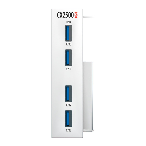
Page 17: Usb Connections
USB 3.0 interface (X700 / X701 / X702 / X703): The CX2500-0070 devices extend the CX20x0 system with four further USB 3.0 interfaces. Each interface has a maximum power output of 900 mA. The maximum total power output is 2000 mA. The interfaces are backward compatible with the USB 2.0 and USB 1.1 standards. - Page 18 In order to ensure trouble-free operation, only cables that comply with the USB 3.0 specification should be used. If the interface is operated in compatibility mode for USB 2.0 / 1.1, the cables must comply with this standard. Version: 1.1 CX2500-0070...
-
Page 19: Commissioning / Configuration
Embedded PC off, since data can be lost from the hard disk by switching off while software is running. Once the software has been stopped, the operating system can be shut down. Only then should the power supply be interrupted. CX2500-0070 Version: 1.1... -
Page 20: Error Handling And Diagnostics
6. Any components / software used The quickest response will come from support / service in your country. Therefore please contact your regional contact. For details please refer to our website at www.beckhoff.de or ask your distribution partner. Version: 1.1... -
Page 21: Decommissioning
In order to release the CX20x0 block, the DIN rail fastening above and below the device must be released. To do this, press the hooks outwards using a screwdriver. An audible click indicates that the device is released. CX2500-0070 Version: 1.1... - Page 22 Subsequently, the system interfaces can be separated again. NOTE Do not use force to open the device! Opening the module housing by force would destroy it. The devices may only be opened by Beckhoff ser- vice personnel. Version: 1.1...
-
Page 23: Appendix
All products of the Embedded PC family are CE, UL and EAC certified. Since the product family is continuously developed further, we are unable to provide a full listing here. The current list of certified products can be found at www.beckhoff.com. FCC Approvals for the United States of America... -
Page 24: Support And Service
Beckhoff's branch offices and representatives Please contact your Beckhoff branch office or representative for local support and service on Beckhoff products! The addresses of Beckhoff's branch offices and representatives round the world can be found on her internet pages: http://www.beckhoff.com You will also find further documentation for Beckhoff components there. - Page 26 More Information: www.beckhoff.com/CX2500-0070 Beckhoff Automation GmbH & Co. KG Hülshorstweg 20 33415 Verl Germany Phone: +49 5246 9630 info@beckhoff.com www.beckhoff.com...
Need help?
Do you have a question about the CX2500-0070 and is the answer not in the manual?
Questions and answers