
Subscribe to Our Youtube Channel
Related Manuals for artisan PB-SIO4A


Summary of Contents for artisan PB-SIO4A
- Page 1 sales@artisantg.com artisantg.com (217) 352-9330 | Visit our website - Click HERE...
- Page 2 PB-SIO4A Quad Serial Port Piggyback RS422/RS485 Manual ID 19958, Rev. Index 0300 Sep 99 The product described in this manual is in compliance with all applied CE stan- dards.
- Page 3 This page was intentionally left blank. ® PEP Modular Computers GmbH...
-
Page 4: Table Of Contents
PB-SIO4A Preface Preface Revision History ............0 - 4 Trademarks ..............0 - 4 Explanation of Symbols ..........0 - 5 For Your Safety............0 - 6 High Voltage Safety Instructions ......0 - 6 Special Handling and Unpacking Instructions ..0 - 6 General Instructions on Usage......... -
Page 5: Revision History
Preface PB-SIO4A Revision History Revision History Manual/Product Title: PB-SIO4A Manual ID Number: 19958 Rev. Date of Brief Description of Changes Board Index Index Issue Preliminary Jul 1992 Correction to Table 2.4.1 Dec 1992 1.0.1 Change to pinouts in Table 2.4.1 and additional... -
Page 6: Explanation Of Symbols
PB-SIO4A Preface Explanation of Symbols CE Conformity This symbol indicates that the item described in this manual is in compliance with all applied CE standards. See also the section “Applied standards” of this manual. Caution! This symbol and title warn you of hazards due to electrical shocks (>... -
Page 7: For Your Safety
Preface PB-SIO4A For your safety Your new PEP product was developed and tested carefully to provide all features necessary to ensure the renown electrical safety requirements. It was also designed for a long fault-free life. However, the life expectancy of your product can be drastically reduced by improper treat- ment during unpacking and installation. -
Page 8: General Instructions On Usage
PB-SIO4A Preface General Instructions on Usage In order to maintain PEP’s product warranty, this product must not be altered or modi- fied in any way. Changes or modifications to the device, which are not explicitly approved by PEP Modular Computers and described in this manual or received from PEP Technical Support as a special handling instruction, will void your warranty. -
Page 9: Two Years Warranty
Preface PB-SIO4A Two Years Warranty PEP Modular Computers grants the original purchaser of PEP products a TWO YEARS LIMITED as described in the following. However, no other warranties that may HARDWARE WARRANTY be granted or implied by anyone on behalf of PEP are valid unless the consumer has the express written consent of PEP Modular Computers. - Page 10 2.2 Software Installation ......... 2 - 4 Chapter 3. Configuration ............3 - 3 3.1 PB-SIO4A Address Map and ID Byte ....3 - 3 3.2 VMEbus Interrupts..........3 - 3 3.3 Jumper Settings..........3 - 4 3.4 Pinouts.............. 3 - 5 19958 , Rev.
- Page 11 Preface PB-SIO4A Chapter 4. Adapter AD-SIO4............4 - 3 4.1 Product Overview ..........4 - 3 4.2 Adapter Overview ..........4 - 3 19958 Page 0 - 10 ® PEP Modular Computers GmbH , Rev. 0300...
- Page 12 1.1.2 Features ................1 - 3 1.2 Board Overview ..............1 - 3 1.3 Functional Block Diagram .............1 - 5 1.4 PB-SIO4A External Interfaceing ...........1 - 5 1.5 Carrier Board External Connectors........1 - 6 1.6 Technical Specifications ............1 - 7 1.7 Applied Standards..............1 - 8 1.7.1 CE Compliance..............1 - 8...
- Page 13 This page was intentionally left blank. ® PEP Modular Computers GmbH...
-
Page 14: Introduction
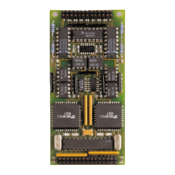
• RS422 • RS485. Any version combination can be installed on a single carrier board. Interfacing to the PB-SIO4A depends on the type of connector provided by the carrier board or optional adapters. 1.1.2 Features General: • Interrupt request line employed, interrupt vector generated by the DUART’s. - Page 15 The optoisolated versions have eight optocouplers which are replaced with wire bridges on the non-optoisolated versions. For operational configuration of this piggyback there are solder jumpers located both on the front and rear side of the board. Figure 1-1: PB-SIO4A Board Front View (Optoisolated Version) Opto- Transmitter isolation...
-
Page 16: Functional Block Diagram
* Optoisolation is optional 1.4 PB-SIO4A External Interfacing Connection of the PB-SIO4A piggyback to external devices is a function of the specific carrier board for the piggyback. In conjunction with the carrier board there are various possibilities for connecting the I/O channels of the piggyback to external devices. -
Page 17: Carrier Board External Connectors
PB-SIO4A Introduction 1.5 Carrier Board External Connectors Figure 1-4: Carrier Board External Connector Types 50-Pin Male 50-Pin Female 50-Pin Male On Board Front Panel Front Panel Page 1 - 6 ® PEP Modular Computers GmbH ID 19958, Rev. 0300... -
Page 18: Technical Specifications
PB-SIO4A Introduction 1.6 Technical Specifications Table 1-1: PB-SIO4A Technical Specification PB-SIO4A Specification Standard RS422 or RS485 Number of Channels four per PB-SIO4A module Controller two MC68681 DUART’s (one pro port pair) Transfer Rates asynchronous: up to 115,200 Baud Programmable Data Format •... -
Page 19: Applied Standards
PB-SIO4A Introduction 1.7 Applied Standards 1.7.1 CE Compliance The PEP Modular Computers’ VME products comply with the requirements of the fol- lowing CE-relevant standards: • Emission EN50081-1 • Immission EN50082-2 • Electrical Safety EN60950 1.7.2 Mechanical Compliance • Mechanical Dimensions IEEE 1101.10... - Page 20 PB-SIO4A Installation Chapter Installation 2.1 Board Installation ..............2 - 3 2.2 Software Installation..............2 - 4 2.2.1 Driver Installation ............2 - 4 ID 19958, Rev. 0300 ® PEP Modular Computers GmbH Page 2 - 1...
- Page 21 This page was intentionally left blank. ® PEP Modular Computers GmbH...
-
Page 22: Installation
• if required, remove the carrier board and optional adapters from the system • ensure the proper orientation of the PB-SIO4A to the carrier board before installing (see appropriate documentation for orientation) • press the piggyback onto the carrier board until fully seated... -
Page 23: Software Installation
PB-SIO4A Installation • if required, repeat this process for a second piggyback on this carrier board • install the carrier board and optional adapters as required • connect external interfacing cables to the carrier board and optional adapters as required •... - Page 24 PB-SIO4A Configuration Chapter Configuration 3.1 PB-SIO4A Address Map and ID Byte ........3 - 3 3.2 VMEbus Interrupts..............3 - 3 3.3 Jumper Settings..............3 - 4 3.4 Pinouts.................. 3 - 5 3.4.1 PB-SIO4A/Carrier Board Connector ST101....3 - 5 3.4.2...
- Page 25 This page was intentionally left blank. ® PEP Modular Computers GmbH...
-
Page 26: Configuration
3. Configuration 3.1 PB-SIO4A Address Map and ID Byte The PB-SIO4A is addressed (odd byte access) by using the carrier board base address and one of the following offsets for the piggyback location: Piggyback location A ( the upper position on the carrier board) -
Page 27: Jumper Settings
Configuration 3.3 Jumper Settings The jumper positions B53 to B69 are located on the rear side of the PB-SIO4A and are solder bridges. Jumpers B51 and B52 are located on the front side of the PB-SIO4A and if installed are wire bridges. They are set at the factory as required and should not be changed. -
Page 28: Pinouts
3.4 Pinouts 3.4.1 PB-SIO4A/Carrier Board Connector ST101 This is a thirty pin, dual row male header connector which provides interfacing between the PB-SIO4A and CPU side of the carrier board. Table 3-2: Pinout of Connector ST101 Signal Signal +5V (Vcc) -
Page 29: Pb-Sio4A/Carrier Board Connector St102
Configuration 3.4.2 PB-SIO4A/Carrier Board Connector ST102 This is a twenty-six pin, dual row male header connector which provides interfacing between the PB-SIO4A and the application side of the carrier board. Table 3-3: Pinout of Connector ST102 Signal Signal +RxD D... -
Page 30: Pb-Sio4A To Carrier Board To Ad-Sio4
PB-SIO4A Configuration 3.4.3 PB-SIO4A to Carrier Board to AD-SIO4 Table 3-4: PB-SIO4A to Carrier Board to AD-SIO4 Pinout Table (Both Positions) POS./ AD-SIO4 Carrier DUART Front Panel Signal ST102 SIO4 Board PINS CON/CH -RxD D 1, 2 +RxD D 25,26... - Page 31 PB-SIO4A Configuration Table 3-4: PB-SIO4A to Carrier Board to AD-SIO4 Pinout Table (Both Positions) POS./ AD-SIO4 DUART Carrier Front Panel Signal ST102 SIO4 Board PINS CON/CH -RxD D 1, 2 +RxD D 25,26 VccE +TxD D -TxD D GndE -RxD C...
- Page 32 PB-SIO4A Adapter AD-SIO4 Chapter Adapter AD-SIO4 4.1 Product Overview ..............4 - 3 4.2 Adapter Overview ..............4 - 3 ID 19958, Rev. 0300 ® PEP Modular Computers GmbH Page 4 - 1...
- Page 33 This page was intentionally left blank. ® PEP Modular Computers GmbH...
- Page 34 24-pin, male dual row connectors for internal connection to the PB-SIO4A carrier board. Connection from the carrier board to the adapter is done via a 50-way, flat band cable with a 50-pin dual row female connector for the carrier board, and two, 24-pin dual row female con- nectors for connection to the adapter.
- Page 35 DO NOT USE (see note below) USE FOR PB-SIO4A Connector BU6 is for use with the PB-SIO4A. Connector BU5 is reserved for use with the PB-SIO4, another serial interface piggyback from PEP. Note! Always ensure that the correct connector of the adapter cable is connected to BU6.
Need help?
Do you have a question about the PB-SIO4A and is the answer not in the manual?
Questions and answers