Table of Contents
Advertisement
Quick Links
Advertisement
Table of Contents

Related Manuals for Lumel SM4


Summary of Contents for Lumel SM4
- Page 1 MODULE OF LOGIC OUTPUTS USEr’S ManUaL...
-
Page 3: Table Of Contents
Contents 1. APPLICATION ................5 2. MODULE SET ................6 3. BASIC REQUIREMENTS AND OPERATIONAL SAFETY .... 6 4. INSTALLATION ................8 4.1. Module fitting ................8 4.2. Terminal description..............9 5. SERVICE ..................12 5.1. Description of the MODBUS protocol implementation ..13 5.2. -
Page 5: Application
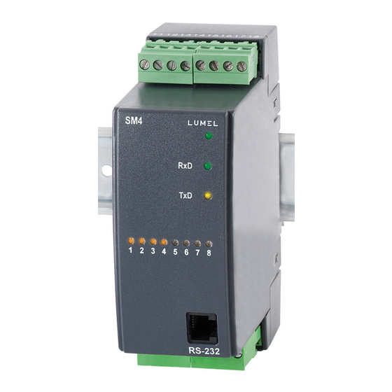
1. APPLICATION The SM4 module of logic outputs is destined to control simple actuators through assignment of logic states received from the master device through the RS-485 interface. The module can have 8 logic outputs or 4 relay outputs (depending on the execution) and RS-485 and RS-232 interfaces with MODBUS RTU and ASCII transmission protocols. -
Page 6: Module Set
Remarks concerning the operator safety: 1. General - The SM4 module is destined to be mounted on a 35 mm mounting rail. - Non-authorized removal of the required housing, inappropriate use, incorrect instal- lation or operation creates the risk of injury to personnel or damage to equipment. - Page 7 - The manufacturer of the measuring system or installed devices is responsible for the compliance with the required limit values demanded by the EMC legislation. 5. Operation - Measuring systems including SM4 modules, must be equipped with protection devices according to the corresponding standard and regulations for prevention of accidents.
-
Page 8: Installation
- Read all product-specific safety and application notes in this user’s manual. Before taking the meter housing out, one must turn the supply off. The removal of the instrument housing during the warranty contract period may cause its cancellation. 4. -
Page 9: Terminal Description
(TxD) - signals the data transmission by the module An example of logic output connection of OC type is presented below Fig.3. Electrical connections of the SM4 binary output module. Fig. 4. Example of logic output connection of OC type. - Page 10 Description of SM4 logic output module - Version with 8 outputs of OC type. Table 1 Terminal Terminal description GND line of logic outputs OUT1 line - output No 1 OUT2 line - output No 2 OUT3 line - output No 3...
-
Page 12: Service
RS-232 and the RS-485 interface. The signal „+” (terminal 10), depending on the version, represents: - for SM4 with 8 outputs of OC type - The terminal to which one must apply the supply voltage for OC output circuits, the level of possible voltage: 5... -
Page 13: Description Of The Modbus Protocol Implementation
One can program all module parameters by means of RS-232 or RS-485. The RS-232 port has constant transmission parameters in accordance with tech- nical data, what enables the connection with the module, even when programmed parameters of the RS-485 digital output are unknown (address, mode, rate). The RS-485 standard allows to the direct connection to 32 devices on a single serial link up to 1200 m. -
Page 14: Description Of The Modbus Protocol Functions
„0” is identified as the data transmission mode (transmission to many devices) 5.2. Description of the MODBUS protocol functions Following functions of the MODBUS protocol has been implemented in the SM4 module series. Description of the MODBUS protocol functions Table 3... - Page 15 Readout of n-registers (code 03h) Function inaccessible in data transmission mode. Example: Readout of 2 registers beginning from the register with the 1DBDh (7613) address: Request: Register Register Number of Number of Checksum Device registers registers Function address address address 52 43 Answer: Device...
- Page 16 Write into n-bit registers (code 0Fh) The function is accessible in the data transmission mode. Example: Write of 2 registers beginning from the register with 0898h (2200) address Request: Register Number of Number of Value for the register Checksum Device address registers Function...
-
Page 17: Map Of Module Registers
Checksum - 2 bytes in case of work in RTU mode - 1 byte in case of work in ASCII mode 5.3. Map of module registers Map of the SM4 series module registers Table 4 Range of Value type Description... -
Page 18: Set Of Module Registers
5.4. Set of module registers Set of registers for readout the SM4 module. Table 5 Quantity name Name 4000 7500 Identifer Constant identifying the device (8C) 4001 7501 Status 1 Status 1 is a register describing current states of binary outputs. - Page 19 Description of the Status2 register Operating mode Baud rate and information unit bits Bit-15...6 Not used State 0 Bit-5...3 Working mode and information unit 000 - interface turned on 001 - 8N1 - ASCII 010 - 7E1 - ASCII 011 - 7O1 - ASCII 100 - 8N2 - RTU 101 - 8E1 - RTU 110 - 8O1 - RTU...
- Page 20 Set of registers for readout and write the SM4 module - in the version with eight outputs of OC type. Table 6 Description Range Symbol Identifier SM4 identifier 4200 7600 Baud rate of RS-485 interface Rate 0... 6 4201 7601...
- Page 21 0... 1 Safety state of the output 8 Safety state Setup time, after which, if there was Admissible 0...65000 not a transmission from SM4, the 4221 7621 silent time switching of outputs in a safe state on the bus follows.
- Page 22 Set of registers for readout and write the SM4 module in the version with four relay outputs. Table 7 Description Range Symbol Identifier SM4 identifier 4200 7600 Baud rate of RS-485 interface Rate 0... 6 4201 7601 transmission (bit/s) 2400...
-
Page 23: Technical Data
7620 – – – Not used Setup time, after which, if there Admissible 0...65000 was not a transmission from SM4, silent time 4221 7621 the switching of outputs in a safe on the bus state follows 6. TECHNICAL DATA Transmission data:... - Page 24 b) RS-232 interface: transmission protocol MODBUS baud rate 9600 address Load capacity of outputs 0.1 A for max. 2 active outputs simultaneously 0.05 A for all active outputs simultaneously Load capacity of relay outputs (voltageless make contacts): - voltage 250 V a.c., 150 V d.c. - current 5 A 30 V d.c., 250 V a.c.
-
Page 25: Before A Damage Will Be Declared
Electromagnetic compatibility: - immunity EN 61000-6-2 - emission EN 61000-6-4 Safety requirements acc. to en EN 61010-1: - installation category III - pollution grade 2 Maximal phase-to-earth voltage: - for supply circuits 300 V - for other circuits 50 V 7. -
Page 26: Ordering Codes
* ........... X The manufacturer will establish the code numbering Ordering example: Code SM4 - 1. 2. 00 .1 means: SM4 - 8-channel module of binary outputs - supply voltage: 85...230...253 V a.c/d.c, - kind of outputs: with 4 relay outputs... -
Page 27: Maintenance And Guarantee
9. MAINTENANCE AND WARRANTY The SM4 module does not require any periodical maintenance. In case of some incorrect operations: 1. After the dispatch date and within the period stated in the warranty card One should return the instrument to the Manufacturer’s Quality Inspection Dept. - Page 28 LUMEL S.A. ul. Słubicka 4, 65-127 Zielona Góra, Poland tel.: +48 68 45 75 100, fax +48 68 45 75 508 www.lumel.com.pl Technical support: tel.: (+48 68) 45 75 143, 45 75 141, 45 75 144, 45 75 140 e-mail: export@lumel.com.pl Export department: tel.: (+48 68) 45 75 130, 45 75 132...
Need help?
Do you have a question about the SM4 and is the answer not in the manual?
Questions and answers