Table of Contents
Advertisement
Quick Links
Advertisement
Table of Contents

Related Manuals for Lumel MR03 Series


Summary of Contents for Lumel MR03 Series
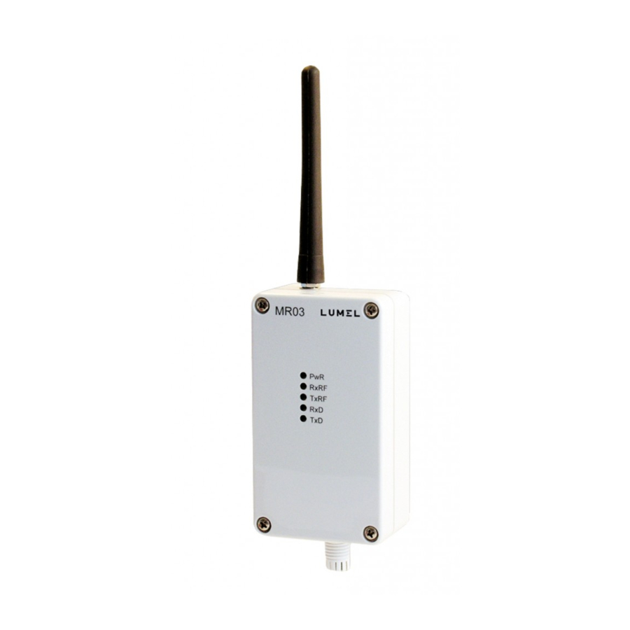
- Page 1 High power radio transmission module MR03 type User’s manual...
-
Page 2: Table Of Contents
CONTENTS 1. A PPLICATION .................5 2. M R03 MODULE SET ...............6 3. I NSTALLATION ................6 3.1 Module assembly ..............6 3.2 Connection diagrams .............7 3.3 Connection way with devices ..........9 3.4 Requirements for lead connections ........10 4. P RINCIPLE OF OPERATION OF MR03 MODULE .......11 4.1 First start of MR03 module ...........12 4.1.1 Installation of the configuration program on a PC ..13 4.1.2 Procedure of the MR03 module configuration ....13 4.1.3 List of displayed errors in the systemic window ....15 4.1.4 Prescription concerning radio transmission or sending-receiving devices which can be used without permission ............16 5. ACCESSORIES ................17 6. T ECHNICAL DATA . -
Page 3: Application
1. APPLICATION The MR03 high power radio transmission module is destined to change the information transmission medium from the cable transmission with RS-232 and RS-485 interface into a wireless transmission in the radio channel in the non-licensed band 869.40 – 869.65 MHZ with the output power 500 mW. The module MR03 finds application in telemetric system applications, in which there is no technical possibilities to conduct a cable to connect de- vices in a wired network. In such cases , the module is used as a bridge which partially will carry out the transmission through the radio way. The maximal operation range of the MR03 module is 1.5 km in average, and depends on the terrain configuration and the applied antenna. Accessible MR03 working modes: transparent, multipoint, point-to-point, allow the creation of an extensive network of radio modules to fit the needs application requirements. Necessary parameter changes to the correct module work are carried out by means of the added configuration program ECon. An exemplary MR03 module application is presented on the fig. 1. 2x input 4-20 mA 2x output 2x output 4-20 mA 4-20 mA... -
Page 4: Mr03 Module Set
2. MR03 MODULE SET The set of the MR03 module is composed of: − MR03 module 1 pc. − Stub antenna with SMA connector 1 pc. − Antenna wire with SMA connector 1 pc. − MR03 user’s manual 1 pc. − warranty card 1 pc. − mini CD with software and user’s manual 1 pc. -
Page 5: Connection Diagrams
Fig. 2 Assembly drawing 3.2. Electrical connections of MR03 module The supply and external signals must be connected in compliance with the drawing 3 and table 1, in which the assignment of individual leads of the MR03 module are described. - Page 6 Fig.3 Description of MR03 leads Description of MR03 module leads Table 1 Terminal Terminal description Supply line (+ for d.c. current supply) Supply line (- for d.c. current line supply) Functional earthing line (d.c. current supply) TxD line of the RS-232 interface RxD line of the RS-232 interface GND line of the RS-232/RS-485 interface Line B of the RS-485 interface Line A of the RS-485 interface Description of MR03 module diodes Table 2 Marking Description PWR Module supply RxRF Reception of radio data TxRF Emision of radio data Reception of data from the serial port Emission of data to the serial port...
-
Page 7: Connection Way With Devices
Description of jumper ZW1 configuration Table 3 Marking Description Short circuit – switching of a substring for line A Short circuit – switching of a substring for line B Short circuit – switching of a 150 Ω termination for line A-B 3.3. Connection way with devices The connection way of the MR03 module to RS-232 or RS-485 interfa- ces is presented on fig. 4 and 5. -
Page 8: Requirements For Lead Connections
3.4. Requirements for lead connections Different interference sources practically occurring, interact with the module in a continuous or pulsing way from the supply network side (because of other device actions). The level of this interference should be reduced to a value lower than the module fastness threshold, first of all through the appropriate installation of the module in the object. In order to obtain a full module resistance against elec- tromagnetic interference in an environment of unknown interference level, it is recommended to observe follo- wing principles: There should be a switch or a circuit breaker in the building installation. -
Page 9: P Rinciple Of Operation Of Mr03 Module
4. PRINCIPLE OF MR03 MODULE OPERATION The MR03 radio transmission module enables the radio com- munication of devices equipped in an RS-232 or RS-485 serial port and USB converter into RS-232 or RS-485, e.g. PD10 or PD12 type. The communication with RS-232 or RS-485 interface can be carried out at rates from 1200 bits to 115.2 kbits. The radio transmission is realized in the shape of data packa- ges. The module allows to transmit data of maximal length 256 bytes. The data transmission is carried out in following way: data bits are col- lected from the serial port and are rewritten to the reception buffer. After an appropriate time (“time out”) from the transmission end, placed data in the buffer are prepared to be transmitted on radio links. In order to transmit data, frames are created, the structure of which depends on the selected working mode. The radio module can work in the transparent or package mode: “multipoint” mode (data are sent from one module and are received by all modules being in the range) or in the “point-to-point” mode, where data are sent to a define device. In transparent mode the data aren’t buffered but sent directly to the radio interface in packets of 60 bytes. -
Page 10: First Start Of Mr03 Module
The current module work state is signaled by lighting diodes: RxD and TxD diodes signals the flow of data through the serial interface, however RxRF and TxRF diodes signal the flow od data through the transmission radio channel. The configuration program takes advantage of one of the accessible computer serial port and the module MR03. The configuration is carried out by means of the ECon configuration pro- gram. The configuration program uses one of the available computer’s serial ports. Configuration can be done via RS-232 and RS-485 interfa- ces of MR03 module. -
Page 11: Installation Of The Configuration Program On A Pc
4.1.1. Installation of the configuration program on a PC The installation relies on copying ECon program files from the added CD to the module set. After installing the program will launch the default browser with the site configuration. 4.1.2. Procedure of MR03 module configuration In order to configure the MR03 module, one must connect it to the com- puter serial port: RS-232, RS-485 or USB converter e.g. - Page 12 Fig. 7. MR03 selection from the device list. After choosing the MR03 device from the list the parameters configura- tion can be done. - Serial port parameters (Fig.8): - baud rate (1200...115200 bit/s) - transimission mode (8N1, 8N2, 8E1, 8O1). Fig. 8. Settings of serial port. - Radio port parameters (Fig.9): - module operating mode, - 3 transmission channels, - 3 power levels.
-
Page 13: List Of Displayed Errors In The Systemic Window
Fig. 9. Settings of radio port. 4.1.3. List of errors displayed in the system window In the „Miscellaneous” of configuration software, one can read the status of errors and perform reset operation or restore the default parameters. (Fig. 10) Fig. 10. View of the status and reset buttons and the default settings. -
Page 14: Prescription Concerning Radio Transmission Or Sending-Receiving Devices Which Can Be Used Without Permission
4.1.4. Prescription concerning radio transmission or sending- receiving devices which can be used without permission. The transmitter activity is defined by the transmitter activity coefficient – we understand by that the proportional transmission time relation in one or many carrier frequencies to the device operation time in 1 hour’ period. For the frequency of the MR03 radio module (869.4 MHz – 869.65 MHz) a large transmission activity has been assigned. It is the activity for which: The transmission efficiency coefficient is higher than 1% and lower than 10%... -
Page 15: Accessories
5. ACCESSORIES The standard MR03 module is equipped with a stub antenna with SMA connector. In order to increase the range it is recommended to use a directional antenna in according to the table 4. Ordering code Picture 0929-300-010 Name Description Antenna Wire: 10m Connector: SMA 10 - elements Frequency range [MHz]: 850-960 Gain [dB] : 13.5 F/B Ratio [dB]: 26 Polarization Type: Vertical Number of elements: 10 Input Impedance [Ω]: 50 Weight [kg] : 0.7 Lenght [m] : 0.7 Beamwidth H [ ] : 32 BeamwidthV [... - Page 16 Ordering code Picture 0929-300-014 Name Description Antenna Wire: 10m Connector: SMA 20 - elements Frequency range [MHz]: 850-960 Gain [dB] : 16.5 F/B Ratio [dB]: 26 Polarization Type: Vertical Number of elements: 20 Input Impedance [Ω]: 50 Weigth [kg] : 0.9 Lenght [m] : 1.7 Beamwidth H [ ] : 25 Beamwidth V [ ] : 26...
-
Page 17: Technical Data
6. TECHNICAL DATA Serial port: RS-232/RS-485 interface - data format 8N1, 8N2, 8E1, 8O1 - baud rate 1200 - 115200 bit/s Radio channel: - carrier frequency 869.425 MHz 869.450 MHz 869.475 MHz 869.500 MHz 869.525 MHz 869.550 MHz 869.575 MHz 869.600 MHz 869.625 MHz - power 20 dBm, 25 dBm, 27 dBm - sensitivity of the receiver... - Page 18 Power absorbed by the module 9 VA Rated operating conditions: − supply voltage 8... 30 V d.c. 12...30 V a.c. 50...60 Hz − ambient temperature - 20...23...55°C − relative air humidity < 95% inadmissible condensation − working position Storage and transport conditions: − ambient temperature - 40... 70°C − relative air humidity < 95% inadmissible condensation Ensured protection degree by the housing: −...
-
Page 19: O Rder Codes
7. MR03 ORDER CODES MR03 high power transmission module XX X Version: standard custom-made * Acceptance tests: without an extra quality inspection certificate with an extra quality inspection certificate acc. to user’s agreement * * after agreeing by the manufacturer CODING EXAMPLE The MR03-00-1 code means: 00 – MR03 module in standard version 1 – with a quality inspection certificate... -
Page 20: Maintenance And Warranty
8. MAINTENANCE AND WARRANTY The MR03 high power radio transmission module does not require any periodical maintenance. In case of some incorrect operations: 1. In the period of 12 months from the date of purchase: One should take the modul down from the installation and return it to the Manufacturer’s Quality Control Dept. If the unit has been used in compliance with the instructions, the Manufacturer warrants to repair it free of charge. 2. After the warranty period: One should turn over the module to repair it in a certified service workshop.
Need help?
Do you have a question about the MR03 Series and is the answer not in the manual?
Questions and answers