Table of Contents
Advertisement
Available languages
Available languages
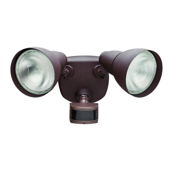
We appreciate the trust and confidence you have placed in Defiant through the purchase of this motion security light.
We strive to continually create quality products designed to enhance your home. Visit us online to see our full line of
products available for your home improvement needs. Thank you for choosing Defiant!
USE AND CARE GUIDE
MOTION SECURITY LIGHT
Questions, problems, missing parts?
Before returning to the store, call Defiant Customer Service
8 a.m.-7 p.m., EST, Monday-Friday, 9 a.m. - 6 p.m., EST, Saturday
1-866-308-3976
HOMEDEPOT.COM
THANK YOU
Item #750199
750964
747373
Model #DF-5718-BK-D
DF-5718-RS-D
DF-5718-WH-D
Advertisement
Chapters
Table of Contents

Related Manuals for Defiant DF-5718-RS-D


Summary of Contents for Defiant DF-5718-RS-D
- Page 1 THANK YOU We appreciate the trust and confidence you have placed in Defiant through the purchase of this motion security light. We strive to continually create quality products designed to enhance your home. Visit us online to see our full line of...
-
Page 2: Table Of Contents
Table of Contents Tools Required ........3 Table of Contents ........2 Hardware Included .........4 Safety Information ........2 Package Contents ........5 Precautions ..........2 Mounting Locations .......5 Warranty ...........2 Installation ..........6 2-Year Warranty ........2 Operation...........7 Specifications ...........3 Care and Cleaning ........10 Pre-Installation .........3 Troubleshooting ........10 Planning Installation ......3 Safety Information... -
Page 3: Specifications
Specifications Up to 100 ft. (30 m) - Varies with surrounding temperature Range Up to 270° Sensing angle Up to 300 watt maximum (Up to 150 watt maximum per bulb Electrical load - incandescent holder) Up to 120 watt maximum PAR38 dimmable LED - Outdoor rated, Electrical load - LED wet rated 120 VAC, 60 Hz... -
Page 4: Hardware Included
Pre-Installation (continued) HARDWARE INCLUDED NOTE: Hardware shown to actual size. FRONT Part Description Quantity Wire connector Rubber plug Mounting bolt Mounting bracket screw Mounting bracket screw Mounting bracket screw Gasket (not to scale) Mounting bracket (not to scale) Plastic hanger (not to scale) -
Page 5: Package Contents
Pre-Installation (continued) PACKAGE CONTENTS Part Description Quantity Bulb holder Canopy Motion sensor Shell MOUNTING LOCATIONS □ Determine the mounting location – a wall or under an eave. □ Position bulb holders (A) in the general direction of the desired light coverage and tighten the lock nuts (1) and the thumb screws (2). -
Page 6: Installation
Installation Installing the Mounting Hanging the Light Fixture Bracket Temporarily □ Insert the small end of the plastic hanger (II) WARNING: Turn the power off at the circuit breaker or through the center hole of the canopy (B) and fuse. Place tape over the circuit breaker switch and verify power is off at the light fixture. -
Page 7: Operation
Installation (continued) Caulking Around the Light Installing the Shells and Bulbs Fixture □ □ Align the three slots on the shell (D) with the Caulk around the canopy (B) and mounting three nibs on the bulb holder (A). surface with silicone sealant (not included). □... - Page 8 Operation (continued) Adjusting the Motion Sensor Setting the Sensor for Testing Detection Zone □ When the “ON-TIME” switch is set to the “TEST” Turn on the circuit breaker or fuse and the light position, the light fixture will operate during the day switch.
- Page 9 Operation (continued) Adjusting the DUALBRITE Adjusting the LAMP MODE Switch Switch The “DUALBRITE” switch determines the amount of The “LAMP MODE” switch determines the way the time the lights stay on at a reduced light level after lights will turn on when motion is detected. sundown.
-
Page 10: Care And Cleaning
Care and Cleaning □ To prolong the original appearance, clean with clear water and a soft, damp cloth only. □ Do not use paints, solvents, or other chemicals on this light fixture. They could cause a premature deterioration of the finish. This is not a defect in the finish and will not be covered by the warranty. □... - Page 11 Troubleshooting (continued) Problem Possible Cause Solution □ □ The lights stay on continuously. A bulb is positioned too close to the Reposition the bulb away motion sensor or pointed at nearby from the motion sensor or objects that cause heat to trigger the nearby objects.
- Page 12 Questions, problems, missing parts? Before returning to the store, call Defiant Customer Service 8 a.m.-7 p.m., EST, Monday-Friday, 9 a.m. - 6 p.m., EST, Saturday 1-866-308-3976 HOMEDEPOT.COM Retain this manual for future use. 205211-07A...
- Page 13 HOMEDEPOT.COM GRACIAS Agradecemos la fe y la confianza que usted ha depositado en Defiant al comprar esta luz de seguridad por movimiento. Procuramos crear continuamente productos de calidad diseñados para mejorar su hogar. Visítenos en internet para ver nuestra línea completa de productos disponibles que necesita para el mejoramiento de su hogar.
-
Page 14: Contenido
Contenido Herramientas Requeridas ....15 Contenido ..........14 Ferretería Incluida ........16 Información de seguridad ......14 Contenido del Paquete ......17 Precauciones ........14 Sitios Para el Montaje ......17 Garantía...........14 Instalación ..........18 2 Años de Garantía .......14 Operación ..........19 Especificaciones ........15 Cuidado y limpieza .........22 Antes de la instalación ......15 Análisis de averías .........22 Planificación de la Instalación .....15... -
Page 15: Especificaciones
Especificaciones Hasta 100 pies (30 m) – Varía con la temperatura circundante Alcance Hasta 270° Ángulo de detección Hasta 300 vatios máximo (Hasta 150 vatios máximo por cada Carga eléctrica-Incandescente porta-bombillas) Hasta 120 vatios máximo PAR38 LED regulable – Clasificado para Carga eléctrica- LED fuera de casa y sitios húmedos 120 VCA, 60 Hz... -
Page 16: Ferretería Incluida
Antes de la instalación (continuación) FERRETERÍA INCLUIDA NOTA: La ferretería se muestra en su tamaño real FRONT Pieza Descripción Cantidad Capuchón para cable Tapón de caucho Tornillo de montaje Tornillo del soporte de montaje Tornillo del soporte de montaje Tornillo del soporte de montaje Empaque (no está... -
Page 17: Contenido Del Paquete
Antes de la instalación (continuación) CONTENIDO DEL PAQUETE Pieza Descripción Cantidad Porta bombilla Escudete Detector de movimiento Casco SITIOS PARA EL MONTAJE □ Determine el sitio para el montaje - una pared o debajo de un alero. □ Coloque los porta bombillas (A) en la dirección general para la cobertura deseada de la luz y apriete las contratuercas (1) y los tornillos de Montaje en... -
Page 18: Instalación
Instalación Instalación del soporte de Cuelgue temporalmente el montaje aparato de luz □ Inserte el extremo corto del colgador plástico ADVERTENCIA: Desconecte la energía eléctrica en el (II) pasándolo por el agujero central del disyuntor o en el fusible. Coloque cinta aislante sobre el interruptor disyuntor y compruebe que no haya energía escudete (B) y del empaque (GG). -
Page 19: Operación
Instalación (continuación) Calafatee alrededor del aparato Instalación de los cascos y las de luz bombillas □ □ Calafatee alrededor del escudete (B) y en Alinee las tres ranuras del casco (D) con los la superficie de montaje con un sellador de tres puntas del porta bombillas (A). - Page 20 Operación (continuación) Calibración del detector para Regulación de la zona de prueba detección del detector de movimiento Cuando el interruptor de “DURACIÓN” (“ON-TIME”) se fija en la posición “PRUEBA” (“TEST”) el aparato de luz □ Conecte el disyuntor o el fusible y el operará...
- Page 21 Operación (continuación) Regulación del interruptor Regulación del interruptor DUALBRITE FASE LÁMPARA El interruptor DUALBRITE determina el lapso de tiempo El interruptor FASE LÁMPARA determina la manera que la luz permanece encendida con un nivel de luz en que las luces se encenderán cuando se detecta reducido luego de la puesta del sol.
-
Page 22: Cuidado Y Limpieza
Cuidado y limpieza □ Para mantener la apariencia original, limpie solamente con agua limpia y un paño húmedo y suave. □ No use pinturas, solventes ni otros químicos en este aparato de luz. Podrían ser la causa de una prematura deterioración del acabado. - Page 23 Análisis de averías (continuación) Problema Causa Probable Solución Las luces se apagan demasiado El aparato de luz puede estar instalado en Vuelva a ubicar el aparato de luz tarde en la calibración un sitio relativamente oscuro. o utilice la calibración 3 horas o 6 crepúsculo-al-amanecer.
- Page 24 ¿Tiene preguntas, problemas o piezas faltantes? Antes de devolverlo a la tienda, llame a Servicio al Cliente de Defiant de 08 a.m.-7 p.m., EST, Lunes - Viernes, 09 a.m.-6 p.m., EST, sábado. 1-866-308-3976 HOMEDEPOT.COM Guarde este manual para uso futuro.
Need help?
Do you have a question about the DF-5718-RS-D and is the answer not in the manual?
Questions and answers
I HAVE MODEL DF-5718-RSD FOR 3 YEARS INSTALLED ON MY BACK PORCH. I BOUGHT NEW BULBS AND INSTALLED THEM IN. THE LIGHTS WILL NOT COME ON. SHOULD I HAVE FIRST TURN OFF THE POWER FROM THE CIRCUIT BREAKER?
@ELMO OCASIO
The provided information does not state that turning off the power from the circuit breaker is required before changing the bulbs. However, it does mention turning the power on at the circuit breaker or fuse during operation. For safety, it is generally recommended to turn off power at the circuit breaker before replacing bulbs, even if not explicitly stated.
This answer is automatically generated