Table of Contents
Advertisement
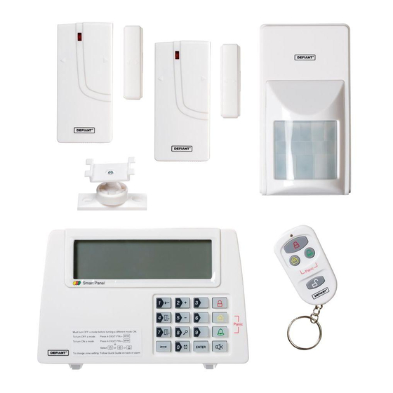
Item #1001-090-469
Model #THD-1000
USE AND CARE GUIDE
WIRELESS HOME PROTECTION SYSTEM
Questions, problems, missing parts? Before returning to the store,
call Customer Service
8 a.m. - 4:30 p.m., CST, Monday - Friday
844-212-0200
HOMEDEPOT.COM
THANK YOU
We appreciate the trust and confidence you have placed in Defiant through the purchase of this wireless home protection system. We strive
to continually create quality products designed to enhance your home. Visit us online to see our full line of products available for your home
improvement needs. Thank you for choosing Defiant!
Advertisement
Table of Contents

Related Manuals for Defiant THD-1000


Summary of Contents for Defiant THD-1000
- Page 1 THANK YOU We appreciate the trust and confidence you have placed in Defiant through the purchase of this wireless home protection system. We strive to continually create quality products designed to enhance your home. Visit us online to see our full line of products available for your home...
-
Page 2: Table Of Contents
Quick Start Guide STEP: 1 STEP: 2 STEP: 4 INSTALLING THE BATTERIES AND SETTING YOUR PIN OPERATING IN ARM MODE POWERING UP THE SYSTEM a. Ensure you are in STANDBY mode by entering the default a. Ensure you are in STANDBY mode by entering your 4-digit □... -
Page 3: Safety Information
SECURITY FEATURE IS EXCLUSIVELY THE 120DB ALARM should be disposed of via a suitable Recycling Center. Do SOUND. DEFIANT IS NOT RESPONSIBLE OR LIABLE FOR ANY not dispose of with your normal household waste. DO NOT DAMAGE, VANDALISM, THEFT OR OTHER ACTIONS THAT MAY BURN. -
Page 4: Warranty
Safety Information (continued) FCC REGULATION This device complies with Part 15 of the FCC Rules. Operation is subject to the following two conditions: (1) This device may not cause harmful interference, and (2) This device must accept any interference received, including interference that may cause undesired operation. -
Page 5: Specifications
Pre-Installation (continued) SPECIFICATIONS Smart Panel Motion Sensor AC adaptor 9V alkaline battery Power Source Power Source 9V Alkaline Battery 433.92MHz +/-0.5MHz Back-up Power RF Working Trans. Freq. Unlimited <110 Degree (@9VDC) Sensor Numbers PIR Detection Angle 4 Jumpers “H”:< 15M(50ft)“M”:< House Code PIR Detection Range 6M(20ft)“L”:<... -
Page 6: Installation
Installation Wall mounting the smart panel and Powering up the Smart Panel tamperproof switch controller □ First cut out the mounting template for the Smart Panel NOTE: The Smart Panel is supplied with a demonstration along with the area which is marked out for the position of switch to show the LCD display panel working while the unit the tamperproof magnet (see below). -
Page 7: Programming Your Pin Number
Installation (continued) UNDERSTANDING THE BATTERY AND AC ADAPTOR ICON Battery Icons: Battery icon shows when the AC power supply is unplugged or interrupted. Full - 9V battery functions as BACK-UP only and the Low symbol means LOW BATTERY. The LCD backlight flashes YELLOW for 30 seconds and the Low battery icon will blink until the new High - battery is replaced or the main power supply (with AC adaptor) is plugged in. -
Page 8: Using The Panic Alarm
Using the Panic Alarm Pressing the buttons at the same time on either the keypad or the key remote control will immediately transmit an alarm signal to the Smart Panel, activating the siren, and transmitting an alarm signal to any optional response devices (Auto Dialer, Outdoor Bell Box &... -
Page 9: Adjusting Exit Delay
Operating in ARM Mode (continued) ADJUSTING EXIT DELAY Step Procedure Example Ensure you are in STANDBY mode by entering the The Smart Panel displays this image when in STANDY mode. One beep default PIN of 1 2 3 4 OR your new 4-digit PIN and indicates that you entered a valid PIN. -
Page 10: Adjusting The Alarm Duration
Operating in ARM Mode (continued) ADJUSTING THE ALARM DURATION Step Procedure Example Ensure you are in STANDBY mode by entering The Smart Panel displays this image when in STANDY mode. One beep the default PIN of 1 2 3 4 OR your new 4-digit indicates that you entered a valid PIN. -
Page 11: Disarming The System
Operating in ARM Mode (continued) When in ARM mode, the Smart Panel flashes RED every 5 seconds, acting as a deterrent to potential intruders. However, if an intruder is detected the panel continuously and rapidly flashes RED. Once an intrusion has occurred (with the zone triggered under ARM status), the alarm siren sounds and the Smart Panel flashes RED every 1.5 seconds and indicates the triggered zone. -
Page 12: Entering Alert Mode
Operating in Standby Mode (continued) Entry delay 30 seconds There are 30 seconds of entry delay time with a visual countdown for disarming. Once an intrusion has occurred (zone triggered under ARM status), the alarm siren sounds for 1 minute and the Smart Panel flashes RED every 1.5 seconds with the triggered zone indicated, until the system is disarmed. -
Page 13: Exiting Alert Mode
Operating in Alert Alert Mode (continued) EXITING ALERT MODE On the Smart Panel: Enter your 4-digit PIN followed by Enter to exit ALERT mode. On the Key Fob Remote Control: Press to exit ALERT mode. ZONE SETTINGS Programming each zone in ALERT mode: Step Procedure Example... -
Page 14: Operating In Home Mode
Operating in Home Mode There are default settings that allow the system to operate after opening the package. These settings can be adjusted to suit your individual requirements. The HOME mode ( ) allows the system to operate in both ARM and ALERT modes in different zones. HOME mode default setting: Sensor Zone... -
Page 15: Installing The Sensors
Operating in Home Mode (continued) Toggle 1 2 3 4 5 6 7 8 to turn each zone in different mode: Press to enter HOME mode. indicates ALERT mode for a zone indicates ARM mode for a zone indicates the zone is turned OFF and the number will not appear The Smart Panel displays this image: Press the Enter button to confirm the setting and return the Smart Panel to STANDBY. -
Page 16: Installing The Motion Sensor
Installing the Sensors (continued) INSTALLING THE MOTION SENSOR The Motion Sensor is designed to sense movement in a given area. NOTE: It is best if pets are not allowed onto higher surfaces so that the sensors are not triggered unnecessarily (no more than 1 m/3.3 ft. high). -
Page 17: Using The Key Fob Remote Control
Installing the Sensors (continued) Step 5: Mounting using Screws □ Hold the enclosed mounting template against the wall at the selected location and mark the points for drilling. □ Drill the holes and insert wall plugs. □ Attach the bracket to the mounting surface with the screws provided. □... -
Page 18: Operating The Key Fob Remote Control
Using the Key Fob Remote Control (continued) OPERATING THE KEY FOB REMOTE CONTROL The remote can be used to arm, disarm, and operate the system instantly. □ ARM – Arms the system, triggering the preset exit delay. When triggered, the Smart Panel’s LED light will flash Red and indicate the triggered zone. -
Page 19: Querying The Id Number Of A Remote Control
Using the Key Fob Remote Control (continued) QUERYING THE ID NUMBER OF A REMOTE CONTROL The ID number of a Remote Control device can be identified as follows: Step Procedure Example Ensure you are in STANDBY mode by entering the TThe Smart Panel displays this image when in STANDY mode. -
Page 20: Zone Code Settings
Zone Code Settings Sensors are supplied with pre-assigned Zone settings to make setup easy – the Door/Window Sensors are pre-assigned to Zones 1 & 2 and the Motion Sensor to Zone 8. To assign a Sensor to a different zone, change the Zone Code on the Sensor by completing these steps: 1. - Page 21 Mounting Template 84mm (3.31inch) Mount tamperproof magnet here 16mm 16mm (0.63inch) (0.63inch) *For details please refer to user guide installation section. HOMEDEPOT.COM Please contact 844-212-0200 for further assistance.
- Page 22 Questions, problems, missing parts? Before returning to the store, call Customer Service 8 a.m. - 4:30 p.m., CST, Monday - Friday 844-212-0200 HOMEDEPOT.COM Retain this manual for future use.
Need help?
Do you have a question about the THD-1000 and is the answer not in the manual?
Questions and answers