Advertisement
1
Installation
A licensed electrician is required to connect this unit to the mains supply.
A lamp (B22 75W Max) is required for the R620 model (not supplied)
1. Determine position in ceiling
where Fanlight is required to be
installed. (Do not install within
120cm of stove or inside a shower
recess). Be certain that the
installation area is not restricted
by roof beams above ceiling.
5. Remove light diffuser and
air-intake grille. Unscrew
the 3 screws on the lip of the
unit until the gap between the
toggles and inner lip of the
unit is greater than the width
of the Gyprock, or other ceiling
material. Fold these toggles in.
Push unit into hole.
2. Use template provided to draw
a circle 300mm in diameter.
To do this insert a thumb tack
in hole at one end and insert
a pencil in the other hole and
scribe a circle.
6. Turn the retention screws
clockwise. The toggles will splay
out. Tightening the retention
screws allows the toggles to
grip the ceiling material.
3. Use electric jig saw or small
hand saw to cut out around this
line. Several holes drilled at a
point inside the circle provides
a convenient starting point for
cutting the panel out.
7. It is recommended that the
three toggles be checked for the
correct clamping by inspection
from above. You may now insert
a globe ≤ 75W into the R620
(not required for the R620LED)
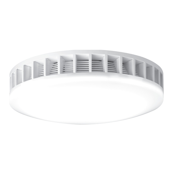
Fanlight
Cat. R620, Standard version
Cat. R620LED, LED Version
Instruction Sheet
4. Remove the terminal cover and
wire according to the diagrams
in section 2. Option 1: This
method of wiring switches
fan and light on and off
simultaneously. Option 2:
Shows how to wire fan and
light separately. This allows the
light (or the fan) to be switched
on independently of the other.
Option 3: Shows the addition of
HPM Cat TX770/1RC time delay
mechanism.
8. Push grille into unit and click into
position. Assemble the diffuser
and round dust seal and twist
into position. To remove this
assembly for cleaning, simply
pull assembly downwards.
Advertisement
Table of Contents

Related Manuals for HPM R620


Summary of Contents for HPM R620
- Page 1 Instruction Sheet Installation A licensed electrician is required to connect this unit to the mains supply. A lamp (B22 75W Max) is required for the R620 model (not supplied) 1. Determine position in ceiling 2. Use template provided to draw 3.
- Page 2 2 pin plug NEUTRAL plug Fan/Light Switch Fan/Light Switch LIGHT NEUTRAL NEUTRAL LOOP LIGHT LIGHT to light to fan LOOP LOOP HPM Cat. TX770/1RC to light to fan to light to fan HPM Cat. TX770/1RC HPM Cat. TX770/1RC...
- Page 3 200mm 200mm Weight (Normal): 3.0kg 3.0kg Product parts INSTALLATION/APPLICATION Terminal block Motor & cover housing Retention screws Fan blade Reflector plug - with lamp holder (R620), or - with LED panel (R620LED) Fan intake grille Light diffuser and seal assembly...
- Page 4 Customer Service Warranty For all Customer Service and Technical Support HPM Legrand warrants this product for a period of 5 years from the please call Monday to Friday during business hours. date of purchase. These goods come with guarantees that cannot...
Need help?
Do you have a question about the R620 and is the answer not in the manual?
Questions and answers