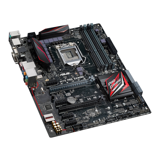
Asus H170 PRO GAMING User Manual
Hide thumbs
Also See for H170 PRO GAMING:
- Manual (92 pages) ,
- Manual (87 pages) ,
- Quick start manual (11 pages)
Table of Contents
Advertisement
Advertisement
Table of Contents

Subscribe to Our Youtube Channel
Related Manuals for Asus H170 PRO GAMING


Summary of Contents for Asus H170 PRO GAMING
- Page 1 H170 PRO GAMING...
- Page 2 Product warranty or service will not be extended if: (1) the product is repaired, modified or altered, unless such repair, modification of alteration is authorized in writing by ASUS; or (2) the serial number of the product is defaced or missing.
-
Page 3: Table Of Contents
Contents Safety information ..................iv About this guide ..................iv Package contents ..................vi H170 PRO GAMING specifications summary ........... vi Chapter 1 Product introduction Before you proceed ..............1-1 Motherboard overview ..............1-1 Central Processing Unit (CPU) ........... 1-3 System memory ................ -
Page 4: Safety Information
Safety information Electrical safety • To prevent electrical shock hazard, disconnect the power cable from the electrical outlet before relocating the system. • When adding or removing devices to or from the system, ensure that the power cables for the devices are unplugged before the signal cables are connected. If possible, disconnect all power cables from the existing system before you add a device. -
Page 5: Conventions Used In This Guide
Refer to the following sources for additional information and for product and software updates. ASUS websites The ASUS website provides updated information on ASUS hardware and software products. Refer to the ASUS contact information. Optional documentation Your product package may include optional documentation, such as warranty flyers, that may have been added by your dealer. -
Page 6: Package Contents
* Hyper DIMM support is subject to the physical characteristics of individual CPUs. Please refer to Memory QVL (Qualified Vendors List) for details. ** Refer to www.asus.com for the latest Memory QVL (Qualified Vendors List). Integrated graphics processor - Intel HD Graphics support ®... -
Page 7: Audio Features
- 2 x USB 3.1 ports at rear (1 Type-A, red; 1 Type-C, black) Intel® H170 Express Chipset - supports ASUS USB 3.1 Boost - 6 x USB 3.0/2.0 ports (4 ports at mid-board; 2 ports at back panel, blue) - 8 x USB 2.0/1.1 ports (6 ports at mid-board;... - Page 8 H170 PRO GAMING specifications summary ASUS Exclusive Features - USB3.1 Boost featuring speedy USB3.1 transmission - Media Streamer ASUS unique - Push Notice features - Disk Unlocker - AI Charger+ - ASUS CPU-Z 1 x PS/2 keyboard/mouse combo port 1 x Optical S/PDIF out...
- Page 9 128 Mb Flash ROM, UEFI AMI BIOS, PnP, DMI 3.0, WfM 2.0, SM BIOS 3.0, ACPI 5.0, Multi-language BIOS, ASUS EZ Flash 3, CrashFree BIOS 3, F11 EZ Tuning Wizard, F6 Qfan Control, F3 My Favorites, F9 Quick Note, F12...
-
Page 11: Chapter 1 Product Introduction
1.2.2 Screw holes Place eight screws into the holes indicated by circles to secure the motherboard to the chassis. Do not overtighten the screws! Doing so can damage the motherboard. ASUS H170 PRO GAMING... -
Page 12: Motherboard Layout
Place this side towards the rear of the chassis 1.2.3 Motherboard layout 24.4cm(9.6in) KBMS_USB78 EATX12V CPU_FAN DIGI CPU_OPT +VRM 1442K USB3.1_EC1 LGA1151 1542 1142 USB3.1_EA1 LAN_USB3_34 LANGuard AUDIO LED_LIGHT CHA_FAN1 PCIEX1_1 Intel I219V PCIEX16_1 Intel ® H170 Super PCIEX1_2 BATTERY SUPREMEFX PCIEX16_2 PCHLED2... -
Page 13: Central Processing Unit (Cpu)
15. USB 2.0 connectors (10-1 pin USB910, USB1112, USB1314) 1-15 16. ROG Extension connector (18-1 pin ROG_EXT) 1-23 17. TPM connector (14-1 pin TPM) 1-22 18. Serial port connector (10-1 pin COM) 1-15 19. Front panel audio connector (10-1 pin AAFP) 1-18 20. SupremeFX LED 1-25 Central Processing Unit (CPU) This motherboard comes with a surface mount LGA1151 socket designed for the 6th Generation Intel Core™ i7 / Core™ i5 / Core™ i3, Pentium and Celeron processors. ® ® ® H170 PRO GAMING CPU socket LGA1151 ASUS H170 PRO GAMING... -
Page 14: Installing The Cpu
Unplug all power cables before installing the CPU. • Ensure that you install the correct CPU designed for the LGA1151 socket only. DO NOT install a CPU designed for LGA1150, LGA1155 and LGA1156 sockets on the LGA1151 socket. • Upon purchase of the motherboard, ensure that the PnP cap is on the socket and the socket contacts are not bent. Contact your retailer immediately if the PnP cap is missing, or if you see any damage to the PnP cap/socket contacts/motherboard components. • Keep the cap after installing the motherboard. ASUS will process Return Merchandise Authorization (RMA) requests only if the motherboard comes with the cap on the LGA1151 socket. • The product warranty does not cover damage to the socket contacts resulting from incorrect CPU installation/removal, or misplacement/loss/incorrect removal of the PnP cap. 1.3.1 Installing the CPU Chapter 1: Product introduction... -
Page 15: Cpu Heatsink And Fan Assembly Installation
1.3.2 CPU heatsink and fan assembly installation Apply the Thermal Interface Material to the CPU heatsink and CPU before you install the heatsink and fan if necessary. ASUS H170 PRO GAMING... - Page 16 To install the CPU heatsink and fan assembly To uninstall the CPU heatsink and fan assembly Chapter 1: Product introduction...
-
Page 17: System Memory
System memory 1.4.1 Overview This motherboard comes with four Double Data Rate 4 (DDR4) Dual Inline Memory Module (DIMM) sockets. A DDR4 module is notched differently from a DDR, DDR2, or DDR3 module. DO NOT install a DDR, DDR2, or DDR3 memory module to the DDR4 slot. According to Intel CPU spec, DIMM voltage below 1.5V is recommended to protect the ® CPU. H170 PRO GAMING 288-pin DDR4 DIMM sockets 1.4.2 Memory configurations You may install 2 GB, 4 GB, 8 GB and 16 GB unbuffered non-ECC DDR4 DIMMs into the DIMM sockets. You can refer to the recommended memory population below. Recommended memory configurations ASUS H170 PRO GAMING... -
Page 18: Installing A Dimm
® motherboard. F or more details, refer to the Microsoft support site at http://support.microsoft. ® com/kb/929605/en-us. • The default memory operation frequency is dependent on its Serial Presence Detect (SPD), which is the standard way of accessing information from a memory module. Under the default state, some memory modules for overclocking may operate at a lower frequency than the vendor-marked value. To operate at the vendor-marked or at a higher frequency, refer to section 2.5 Ai Tweaker menu for manual memory frequency adjustment. • Always install the DIMMS with the same CAS Latency. For an optimum compatibility, we recommend that you install memory modules of the same version or data code (D/C) from the same vendor. Check with the vendor to get the correct memory modules. • For system stability, use a more efficient memory cooling system to support a full memory load (4 DIMMs) or overclocking condition. Visit the ASUS website at www.asus.com for the latest QVL. 1.4.3 Installing a DIMM Chapter 1: Product introduction... -
Page 19: Expansion Slots
Unplug the power cord before adding or removing expansion cards. Failure to do so may cause you physical injury and damage motherboard components. 1.5.1 Installing an expansion card To install an expansion card: Before installing the expansion card, read the documentation that came with it and make the necessary hardware settings for the card. Remove the system unit cover (if your motherboard is already installed in a chassis). Remove the bracket opposite the slot that you intend to use. Keep the screw for later use. ASUS H170 PRO GAMING... -
Page 20: Pci Express 3.0 X16 Slots
Align the card connector with the slot and press firmly until the card is completely seated on the slot. Secure the card to the chassis with the screw you removed earlier. Replace the system cover. 1.5.2 Configuring an expansion card After installing the expansion card, configure it by adjusting the software settings. Turn on the system and change the necessary BIOS settings, if any. See Chapter 2 for information on BIOS setup. Assign an IRQ to the card. Install the software drivers for the expansion card. When using PCI cards on shared slots, ensure that the drivers support “Share IRQ” or that the cards do not need IRQ assignments. Otherwise, conflicts will arise between the two PCI groups, making the system unstable and the card inoperable. 1.5.3 PCI Express 3.0 x1 slots This motherboard supports PCI Express x1 network cards, SCSI cards, and other cards that comply with the PCI Express specifications. 1.5.4 PCI Express 3.0 x16 slots This motherboard has two PCI Express 3.0 x16 slots that support PCI Express 3.0 x16 graphic cards complying with the PCI Express specifications. PCI Express operating mode VGA configuration PCIe 3.0 x16_1 (gray) PCIe 3.0 x16_2 (black) -
Page 21: Clear Rtc Ram
– – – – Controller XHCI Controller shared – – – – – – – Headers and Jumpers Clear RTC RAM (2-pin CLRTC) This header allows you to clear the Real Time Clock (RTC) RAM in CMOS. You can clear the CMOS memory of date, time, and system setup parameters by erasing the CMOS RTC RAM data. The onboard button cell battery powers the RAM data in CMOS, which include system setup information such as system passwords. CLRTC PIN 1 H170 PRO GAMING Clear RTC RAM ASUS H170 PRO GAMING 1-11... -
Page 22: Cpu Over Voltage Jumper
Turn OFF the computer and unplug the power cord. Use a metal object such as a screwdriver to short the two pins. Plug the power cord and turn ON the computer. Hold down the <Del> key during the boot process and enter BIOS setup to re- enter data. • If the steps above do not help, remove the onboard battery and short the two pins again to clear the CMOS RTC RAM data. After clearing the CMOS, reinstall the battery. • You do not need to clear the RTC when the system hangs due to overclocking. For system failure due to overclocking, use the CPU Parameter Recall (C.P.R.) feature. Shut down and reboot the system, then the BIOS automatically resets parameter settings to default values. CPU Over Voltage jumper (3-pin CPU_OV) The CPU Over Voltage jumper allows you to set a higher CPU voltage for a flexible overclocking system, depending on the type of the installed CPU. To gain more CPU voltage setting, insert the jumper to pins 2-3. To go back to its default CPU voltage setting, insert the jumper to pins 1-2. CPU_OV Disable Enable (default setting) H170 PRO GAMING CPU_OV setting 1-12 Chapter 1: Product introduction... -
Page 23: Connectors
1Gbps connection (Blinking) LAN port Orange Ready to (Blinking then wake up from steady) S5 mode Center / Subwoofer port (orange). This port connects the center/subwoofer speakers. Rear Speaker Out port (black). This port connects the rear speakers in a 4.1 channel, 5.1 channel, or 7.1 channel audio configuration. Line In port (light blue). This port connects to the tape, CD, DVD player, or other audio sources. Line Out port (lime). This port connects to a headphone or a speaker. In the 4.1, 5.1 and 7.1-channel configurations, the function of this port becomes Front Speaker Out. ASUS H170 PRO GAMING 1-13... - Page 24 Microphone port (pink). This port connects to a microphone. Refer to the audio configuration table for the function of the audio ports in 2.1, 4.1, 5.1, or 7.1-channel configuration. Optical S/PDIF out port. This port allows you to connect your PC to amplified speakers, headphones, or Sony/Phillips Digital Interconnect Format (S/PDIF) compliant devices. Audio 2.1, 4.1, 5.1, or 7.1-channel configuration Headset Port 4.1-channel 5.1-channel 7.1-channel 2-channel Light Blue Line In Line In Line In Line In Lime Line Out Front Speaker Out Front Speaker Out Front Speaker Out Pink Mic In Mic In...
-
Page 25: Internal Connectors
1.7.2 Internal connectors Serial port connector (10-1 pin COM) This connector is for a serial (COM) port. Connect the serial port module cable to this connector, then install the module to a slot opening at the back of the system chassis. PIN 1 H170 PRO GAMING Serial port (COM) connector The COM module is purchased separately. USB 2.0 connectors (10-1 pin USB910, USB1112, USB1314) These connectors are for USB 2.0 ports. Connect the USB module cable to any of these connectors, then install the module to a slot opening at the back of the system chassis. These USB connectors comply with USB 2.0 specifications and supports up to 480Mbps connection speed. USB910 USB1112 USB1314 PIN 1 PIN 1 PIN 1 H170 PRO GAMING USB2.0 connectors... - Page 26 IntA_P1_SSTX+ IntA_P2_SSTX+ IntA_P1_D- IntA_P2_D- IntA_P1_D+ IntA_P2_D+ USB3_34 PIN 1 H170 PRO GAMING USB3.0 Front panel connectors • These connectors are based on xHCI specification. We recommend you to install the related driver to fully use the USB3.0 ports under Windows ® • The plugged USB 3.0 device will run on xHCI mode. Thermal sensor connector (2-pin T_SENSOR) This connector is for the thermistor cable that allows you to monitor the temperature of your motherboard’s critical components and connected devices.
- Page 27 +5 Volts Power OK -5 Volts +5 Volts +5 Volts PSON# +3 Volts -12 Volts +3 Volts +3 Volts PIN 1 H170 PRO GAMING ATX power connectors • For a fully configured system, we recommend that you use a power supply unit (PSU) that complies with ATX 12V Specification 2.0 (or later version) and provides a minimum power of 350 W. • DO NOT forget to connect the 4-pin/8-pin EATX +12V power plug. Otherwise, the system will not boot up. • We recommend that you use a PSU with higher power output when configuring a system with more power-consuming devices or when you intend to install additional devices. The system may become unstable or may not boot up if the power is...
- Page 28 Front panel audio connector (10-1 pin AAFP) This connector is for a chassis-mounted front panel audio I/O module that supports either HD Audio or legacy AC`97 audio standard. Connect one end of the front panel audio I/O module cable to this connector. AAFP PIN 1 HD-audio-compliant Legacy AC’97 pin definition compliant definition H170 PRO GAMING Front panel audio connector • We recommend that you connect a high-definition front panel audio module to this connector to avail of the motherboard’s high-definition audio capability. • If you want to connect a high-definition front panel audio module to this connector, set the Front Panel Type item in the BIOS setup to [HD Audio]. If you want to connect an AC’97 front panel audio module to this connector, set the item to [AC97]. By default, this connector is set to [HD Audio]. See section 2.6.7 Onboard Devices Configuration for details.
- Page 29 CPU_FAN CPU_OPT CHA_FAN3 CHA FAN PWR CHA FAN IN CHA_FAN1 CHA_FAN2 EXT_FAN PIN 1 H170 PRO GAMING Fan connectors • Do not forget to connect the fan cables to the fan connectors. Insufficient air flow inside the system may damage the motherboard components. These are not jumpers! Do not place jumper caps on the fan connectors! • Ensure that the CPU fan cable is securely installed to the CPU fan connector. • The CPU_FAN connector supports a CPU fan of maximum 1 A (12 W) fan power. •...
- Page 30 RSATA_TXP4 RSATA_TXN3 RSATA_TXN4 RSATA_RXN3 RSATA_RXN4 RSATA_RXP3 RSATA_RXP4 SATA6G_5 SATA6G_6 RSATA_TXP5 RSATA_TXP6 RSATA_TXN5 RSATA_TXN6 RSATA_RXN5 RSATA_RXN6 RSATA_RXP5 RSATA_RXP6 H170 PRO GAMING Intel SATA 6.0Gb/s connectors ® • You must install Windows. XP Service Pack 3 or later version before using Serial ATA hard disk drives. • When using hot-plug and NCQ, set the SATA Mode Selection item in the BIOS to [AHCI]. See section 2.6.5 SATA Configuration for details. 1-20 Chapter 1: Product introduction...
-
Page 31: System Panel Connector
SPEAKER PWR_SW PIN 1 +HDD_LED- RESET +PWR_LED- * Requires an ATX power supply H170 PRO GAMING System panel connector • System power LED (4-pin +PWR_LED-) This 2-pin connector is for the system power LED. Connect the chassis power LED cable to this connector. The system power LED lights up when you turn on the system power, and blinks when the system is in sleep mode. •... - Page 32 TPM connector (14-1 pin TPM) This connector supports a Trusted Platform Module (TPM) system, which can securely store keys, digital certificates, passwords, and data. A TPM system also helps enhance network security, protects digital identities, and ensures platform integrity. PIN 1 H170 PRO GAMING TPM connector The TPM module is purchased separately. LED Light connector (3-pin LED_LIGHT) This connector is for the LED light. LED_LIGHT PIN 1 H170 PRO GAMING LED_LIGHT connector 1-22 Chapter 1: Product introduction...
- Page 33 ROG Extension - ROG_EXT connector (18-1 pin ROG_EXT) This connector is for the Front Base. ROG_EXT H170 PRO GAMING ROG_EXT connector • The Front Base is purchased separately. • Visit www.asus.com for more information about the Front Base. ASUS H170 PRO GAMING 1-23...
-
Page 34: Standby Power Led
H170 PRO GAMING Onboard LED Model Name LEDs The Model Name LEDs are a group of five small LEDs, located right below the printed model name. The LEDs light up in the following two modes to highlight the model name. Model Name LED H170 PRO GAMING Model Name LED Lighting Lighting mode Description Breathing mode The LEDs blink intermittently. Still mode The LEDs become solid red. - Page 35 SupremeFX LED The SupremeFX LED lights up in the following three ways to bring you an ultimate lighting effect. This LED also outlines the separation of the audio components from the rest of your motherboard. SupremeFX LED H170 PRO GAMING SupremeFX LED Lighting Lighting mode Description Breathing mode The LED blinks intermittently. Flowing mode The LED lights up and dims like flowing water.
-
Page 36: Software Support
Motherboard settings and hardware options vary. Refer to your OS documentation for detailed information. 1.9.2 Support DVD information The Support DVD that comes with the motherboard package contains the drivers, software applications, and utilities that you can install to avail all motherboard features. The contents of the Support DVD are subject to change at any time without notice. Visit the ASUS website at www.asus.com for updates. To run the Support DVD Place the Support DVD into the optical drive. If Autorun is enabled in your computer, the DVD automatically displays the lists of the unique features of your ASUS motherboard. Click the Drivers, Utilities, Manual, or Specials tabs to display their respective menus. The following screen is for reference only. Click to install Select an item/ subitem that you Click a tab to... -
Page 37: Chapter 2 Bios Information
Managing and updating your BIOS Save a copy of the original motherboard BIOS file to a USB flash disk in case you need to restore the BIOS in the future. Copy the original motherboard BIOS using the ASUS Update utility. -
Page 38: Asus Ez Flash
2.1.2 ASUS EZ Flash 3 The ASUS EZ Flash 3 feature allows you to update the BIOS without using an OS‑based utility. • Ensure to load the BIOS default settings to ensure system compatibility and stability. Select the Load Optimized Defaults item under the Exit menu. See section 2.10 Exit Menu for details. -
Page 39: Asus Crashfree Bios 3 Utility
2.1.3 ASUS CrashFree BIOS 3 utility The ASUS CrashFree BIOS 3 is an auto recovery tool that allows you to restore the BIOS file when it fails or gets corrupted during the updating process. You can restore a corrupted BIOS file using the motherboard support DVD or a USB flash drive that contains the updated BIOS file. - Page 40 ENTER to select boot device ESC to boot using defaults P2: ST3808110AS (76319MB) aigo miniking (250MB) UEFI: (FAT) ASUS DRW-2014L1T(4458MB) P1: ASUS DRW-2014L1T(4458MB) UEFI: (FAT) aigo miniking (250MB) Enter Setup When the booting message appears, press <Enter> within five (5) seconds to enter FreeDOS prompt.
- Page 41 DO NOT shut down or reset the system while updating the BIOS to prevent system boot failaure. Ensure to load the BIOS default settings to ensure system compatibility and stability. Select the Load Optimized Defaults item under the Exit BIOS menu. See section 2.10 Exit Menu for details. ASUS H170 PRO GAMING 2‑5...
-
Page 42: Bios Setup Program
The BIOS setup screens shown in this section are for reference purposes only, and may not exactly match what you see on your screen. • Visit the ASUS website at www.asus.com to download the latest BIOS file for this motherboard. •... - Page 43 Selects the boot Click the button to manually system device priority tune the fans Displays the Loads optimized Advanced mode default settings menus The boot device options vary depending on the devices you installed to the system. ASUS H170 PRO GAMING 2‑7...
-
Page 44: Advanced Mode
2.2.2 Advanced Mode The Advanced Mode provides advanced options for experienced end‑users to configure the BIOS settings. The figure below shows an example of the Advanced Mode. Refer to the following sections for the detailed configurations. To access the EZ Mode, click EzMode(F7) or press <F7>. Q-Fan control EZ Tuning Wizard... -
Page 45: Menu Bar
This button above the menu bar allows you to view and tweak the overclocking settings of your system. It also allows you to change the motherboard’s SATA mode from AHCI to RAID mode. Refer to section 2.2.4 EZ Tuning Wizard for more information. ASUS H170 PRO GAMING... -
Page 46: Hot Keys
Quick Note (F9) This button above the menu bar allows you to key in notes of the activities that you have done in BIOS. • The Quick Note function does not support the following keyboard functions: delete, cut, copy and paste. •... -
Page 47: Qfan Control
CPU and chassis fans. Click to select a fan to be configured Select a profile to apply Click to apply to your fans the fan setting Click to undo Click to the changes go back to main menu ASUS H170 PRO GAMING 2-11... -
Page 48: Configuring Fans Manually
Configuring fans manually Select Manual from the list of profiles to manually configure your fans’ operating speed. Click to manually Speed points configure your fans To configure your fans: Select the fan that you want to configure and to view its current status. Click and drag the speed points to adjust the fans’... -
Page 49: Ez Tuning Wizard
Select the CPU fan type (Box cooler, Tower cooler, or Water cooler) that you installed then click Next. If you are not sure of the CPU fan type, click I’m not sure. The system automatically detects the CPU fan type. Click Next then click Yes to confirm auto‑tuning. ASUS H170 PRO GAMING 2‑13... -
Page 50: Creating Raid
Creating RAID To create RAID: Press <F11> on your keyboard or click from the BIOS screen to open EZ Tuning Wizard screen. Click RAID then click Next. • Ensure that your HDDs have no existing RAID volumes. • Ensure to connect your HDDs to Intel SATA connectors. -
Page 51: My Favorites
My Favorites MyFavorites is your personal space where you can easily save and access your favorite BIOS items. ASUS H170 PRO GAMING 2‑15... - Page 52 Adding items to My Favorites To add BIOS items: Press <F3> on your keyboard or click from the BIOS screen to open Setup Tree Map screen. On the Setup Tree Map screen, select the BIOS items that you want to save in MyFavorites screen.
-
Page 53: Main Menu
RAM to clear the BIOS password. See section 1.6 Headers and Jumpers for information on how to erase the RTC RAM. • The Administrator or User Password items on top of the screen show the default Not Installed. After you set a password, these items show Installed. ASUS H170 PRO GAMING 2‑17... -
Page 54: Administrator Password
Administrator Password If you have set an administrator password, we recommend that you enter the administrator password for accessing the system. To set an administrator password: Select the Administrator Password item and press <Enter>. From the Create New Password box, key in a password, then press <Enter>. Confirm the password when prompted. -
Page 55: Ai Tweaker Menu
Select [Auto] to apply the CPU default Turbo Ratio setting or manually assign a 2‑Core Limit value that must be higher than or equal to the 3‑Core Ratio Limit. If you assign a value for 2‑Core Ratio Limit, do not set the 1‑Core Ratio Limit to [Auto]. ASUS H170 PRO GAMING 2-19... - Page 56 2.5.6 EPU Power Saving Mode [Disabled] ASUS EPU (Energy Processing Unit) sets the CPU in its minimum power consumption settings. Enable this item to set lower CPU VCCIN and Vcore voltages and achieve the best energy saving condition. Configuration options: [Disabled] [Enabled]...
-
Page 57: Dram Timing Control
This item allows you to set a higher frequency for a quicker transient response speed. Use the <+> and <‑> keys to adjust the value. The values range from 250KHz to 500KHz with a 50KHz interval. ASUS H170 PRO GAMING 2-21... - Page 58 VRM Spread Spectrum [Disabled] This item allows you to enable the spread spectrum to enhance system stability. Configuration options: [Enabled] [Disabled] CPU Power Duty Control [T.Probe] DIGI + VRM Duty control adjusts the current and thermal conditions of every component’s phase.
- Page 59 2.5.11 CPU Core/Cache Current Limit Max. [Auto] Allows you to configure a higher current limit to prevent a frequency or power throttling when overclocking. The values range from 0.00A to 255.50A with a 0.25A interval. ASUS H170 PRO GAMING 2‑23...
- Page 60 2.5.12 CPU Graphics Current Limit Max. [Auto] Allows you to configure a higher current limit to prevent a frequency or power throttling when overclocking. The values range from 0.00A to 255.50A with a 0.25A interval. 2.5.13 Min. CPU Cache Ratio [Auto] Allows you to configure the minimum possible CPU cache ratio.
- Page 61 DRAM REF Voltage Control The subitems in this menu allows you to set the DRAM reference voltage on the control lines from the memory bus. You can use the <+> or <‑> keys to adjust the value. ASUS H170 PRO GAMING 2‑25...
-
Page 62: Advanced Menu
Advanced menu The Advanced menu items allow you to change the settings for the CPU and other system devices. Be cautious when changing the settings of the Advanced menu items. Incorrect field values can cause the system to malfunction. 2.6.1 CPU Configuration The items in this menu show the CPU‑related information that the BIOS automatically detects. -
Page 63: Cpu Power Management Configuration
The following items appear only when you set the CPU C states to [Enabled]. Enhanced C-states [Enabled] [Enabled] Enables enhanced C1 state. [Disabled] Disables enhanced C1 state. CPU C3 Report [Enabled] Allows you to disable or enable the CPU C3 report to OS. Configuration options: [Enabled] [Disabled] ASUS H170 PRO GAMING 2‑27... -
Page 64: Platform Misc Configuration
ASPM to take effect. Configuration options: [Disabled] [L1] PEG - ASPM [Disabled] This item allows you to select the ASPM state for energy‑saving conditions, or use the ASUS optimized energy saving profile. Configuration options: [Disabled] [Auto] [ASPM L0s] [ASPM L1] [ASPM L0sL1] 2‑28... -
Page 65: Graphics Configuration
Allows you to configure the PCIEx16 speed for slot 2. Configuration options: [Auto] [Gen1] [Gen2] [Gen3] Memory Configuration Allows you to configure the memory configuration parameters. Memory Remap [Enabled] Allows you to enable or disable memory remap above 4GB. Configuration options: [Enabled] [Disabled] ASUS H170 PRO GAMING 2-29... -
Page 66: Pch Configuration
SATA Port items show Not Present if no SATA device is installed to the corresponding SATA port. Hyper kit Mode [Disabled] [Enabled] Enables this option for ASUS Hyper kit card. [Disabled] Disables this option for M.2 devices. SATA Controller(s) [Enabled] Enables or disables onboard the SATA device. -
Page 67: Usb Configuration
Allow you to set the model name LED mode. Configuration options: [Disabled] [Still Mode] [Breathing Mode] HD Audio Controller [Enabled] [Enabled] Enables the HD Audio Device. [Disabled] Disables the HD Audio Device. The following item appears only when you set the HD Audio Controller item to [Enabled]. ASUS H170 PRO GAMING 2‑31... - Page 68 Front Panel Type [HD Audio] Allows you to set the front panel audio connector (AAFP) mode to legacy AC’97 or high‑definition audio depending on the audio standard that the front panel audio module supports. [HD Audio] Sets the front panel audio connector (AAFP) mode to high definition audio.
-
Page 69: Serial Port Configuration
Enables Ring to generate a wake event. Power On By RTC [Disabled] [Disabled] Disables RTC to generate a wake event. [Enabled] When set to [Enabled], the items RTC Alarm Date (Days) and Hour/ Minute/Second will become user‑configurable with set values. ASUS H170 PRO GAMING 2‑33... -
Page 70: Monitor Menu
2.6.9 Network Stack Configuration Network Stack [Disabled] This item allows user to disable or enable the UEFI network stack. Configuration options: [Disabled] [Enabled] The following items appear only when you set the previous item to [Enabled]. Ipv4 / Ipv6 PXE Support [Enabled] This item allows you to enable or disable the Ipv4/Ipv6 PXE wake event. - Page 71 Use the <+> and <‑> keys to adjust the maximum CPU fan duty cycle. The values range from 20% to 100%. When the CPU temperature reaches the upper limit, the CPU fan will operate at the maximum duty cycle. ASUS H170 PRO GAMING 2‑35...
- Page 72 CPU Middle Temperature [25] Use the <+> or <‑> keys to set the value for CPU Middle Temperature. The range of the values depends on the CPU installed. CPU Fan Middle Duty Cycle(%) [20] Use the <+> or <‑> keys to adjust the CPU fan middle duty cycle. The values range from 20% to 100%.
- Page 73 [Silent] Sets to [Silent] to minimize the fan speed for quiet extension fan operation. [Turbo] Sets to [Turbo] to achieve maximum extension fan speed. [Manual] Sets to [Manual] to assign detailed fan speed control parameters. ASUS H170 PRO GAMING 2‑37...
- Page 74 The following items appear only when you set Extension Fan 1/2/3 Profile to [Manual]. Extension Fan 1/2/3 Upper Temperature [70] Use the <+> or <‑> keys to adjust the upper limit of the extension fan temperature. The values range from 20°C to 75°C. Extension Fan 1/2/3 Max.
-
Page 75: Boot Menu
POST waiting time to easily enter the BIOS setup. You can only execute the POST delay time during Normal Boot. The values range from 0 to 10 seconds. This feature will only work under normal boot. ASUS H170 PRO GAMING 2‑39... - Page 76 [Force BIOS] The third‑party ROM messages will be displayed during POST. [Keep Current] Disables the ROM messages and displays only the ASUS logo during POST. Interrupt 19 Capture [Disabled] This item allows you to trap Interrupt 19 by the option ROMs. Configuration options:...
-
Page 77: Secure Boot
This item allows you to delete the PK from your system. Once the PK is deleted, all the system’s Secure Boot keys will not be active. The PK file must be formatted as a public key certificate or UEFI variable structure with time‑based authenticated variable. ASUS H170 PRO GAMING 2-41... - Page 78 KEK Management The KEK (Key‑exchange Key or Key Enrollment Key) manages the Signature database (db) and Revoked Signature database (dbx). Key‑exchange Key (KEK) refers to Microsoft Secure Boot Key‑Enrollment Key (KEK). ® Set New Key Allows you to load the downloaded KEK from a USB storage device. Append Key Allows you to load the additional KEK from a storage device for an additional db and dbx loaded management.
-
Page 79: Boot Option Priorities
OS in Safe Mode, press <F8 > after POST (Windows 8 not supported). • To select the boot device during system startup, press <F8> when ASUS Logo appears. 2.8.12 Boot Override These items displays the available devices. The number of device items that appears on the screen depends on the number of devices installed in the system. -
Page 80: Tool Menu
<Enter> to display the submenu. 2.9.1 ASUS EZ Flash 3 Utility Allows you to run ASUS EZ Flash 3. Press [Enter] to launch the ASUS EZ Flash 3 screen. For more details, see section 2.1.2 ASUS EZ Flash 3. 2.9.2 Setup Animator [Disabled] Enables or disables the Setup animator. -
Page 81: Exit Menu
<Esc>, a confirmation window appears. Select OK to discard changes and exit. Launch EFI Shell from USB drives This option allows you to attempt to launch the EFI Shell application (shellx64.efi) from one of the available USB devices. ASUS H170 PRO GAMING 2‑45... -
Page 82: Installing An Operating System
Connect the USB ODD or USB storage device to your 100 series platform. Insert the ASUS support DVD into a SATA ODD on your 100 series platform. Power on your system and press F8 during POST (Power‑On Self Test) to enter the boot screen. - Page 83 The USB 3.0 driver will be loaded automatically during installation startup. The “Setup is starting...” screen will show up if the USB 3.0 driver is loaded correctly. Follow the onscreen instructions to complete the Windows 7 installation. ® ASUS H170 PRO GAMING 2‑47...
- Page 84 ® source using a third‑party ISO software. Copy both “Auto_Unattend.xml” and “Auto_Unattend” folder from the root directory of the ASUS supporting DVD to your system. Edit the ISO file and add both “Auto_Unattend.xml” and “Auto_Unattend” folder into the ISO file.
- Page 85 1 x USB storage device (8 GB or more) Insert the Windows 7 installation DVD. ® Launch the ASUS EZ Installer located on the ASUS support DVD. Select a method of creating a modified Windows 7 installation file: ® •...
- Page 86 ‑ Select the source of the Windows 7 installation disk then click Next. ® ‑ Select the USB storage device and click next. Click the refresh icon if the USB storage device is not displayed. ‑ Click Yes to clear the contents on the USB storage device and create a bootable USB device.
- Page 87 ® - Select Windows 7 OS disk to ISO file then click Next. ‑ Check I agree and then click Next. ‑ Select the source of the Windows 7 installation disk then click Next. ® ASUS H170 PRO GAMING 2‑51...
- Page 88 ‑ Select the folder to save the modified Windows 7 installation ISO file and click ® Next. ‑ Once completed, click OK to finish. ‑ Burn this ISO file onto an empty DVD to create a modified Windows ® installation DVD. Insert the modified Windows 7 installation DVD into an ODD or connect the USB ®...
-
Page 89: Appendices
: (1) cet appareil ne doit pas provoquer d’interférences et (2) cet appareil doit accepter toute interférence, y compris celles susceptibles de provoquer un fonctionnement non souhaité de l’appareil. ASUS H170 PRO GAMING... -
Page 90: Canadian Department Of Communications Statement
ASUS Recycling/Takeback Services ASUS recycling and takeback programs come from our commitment to the highest standards for protecting our environment. We believe in providing solutions for you to be able to responsibly recycle our products, batteries, other components as well as the packaging materials. - Page 91 CE. das Diretivas da CE. Para mais detalhes, consulte a Declaração de Компания ASUS заявляет, что это устройство соответствует основным Conformidade CE. требованиям и другим соответствующим условиям европейских Română Prin prezenta, AsusTek Inc. declară faptul că acest dispozitiv директив.
-
Page 92: Asus Contact Information
+1-510-739-3777 +1-510-608-4555 Web site http://www.asus.com/us/ Technical Support Support fax +1-812-284-0883 General support +1-812-282-2787 Online support http://www.service.asus.com/ ASUS COMPUTER GmbH (Germany and Austria) Address Harkort Str. 21-23, D-40880 Ratingen, Germany +49-2102-959931 Web site http://www.asus.com/de Online contact http://eu-rma.asus.com/sales Technical Support Telephone +49-2102-5789555... - Page 93 ASUS H170 PRO GAMING...
Need help?
Do you have a question about the H170 PRO GAMING and is the answer not in the manual?
Questions and answers