Table of Contents
Advertisement
Quick Links
How to Set Up a SCADAmetrics
®
Signalizer with the
Neptune
®
C&I MACH 10
®
The following document provides information related to the configuration and use of the
SCADAmetrics Signalizer™ industrial output module (IOM) with Neptune's C&I MACH 10 ultrasonic
water meter. For further troubleshooting or additional information specific to The Signalizer™
product, contact SCADAmetrics at 636.405.7101, via email at jim@scadametrics.com, or online at
www.scadametrics.com.
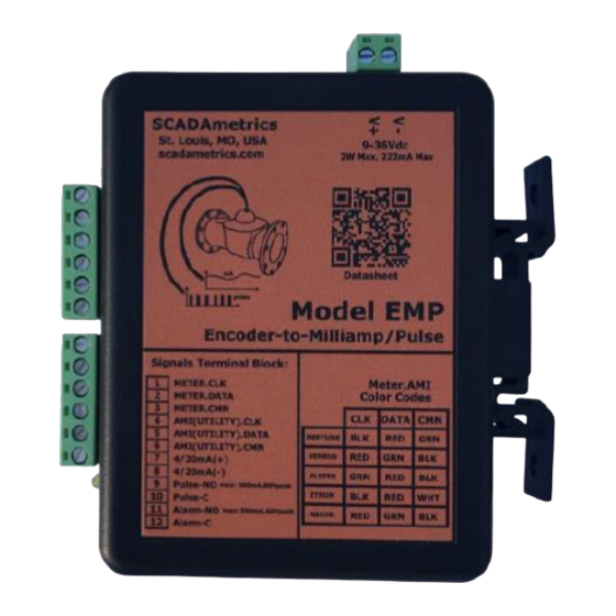
The Signalizer IOM Product Overview
The Signalizer from SCADAmetrics is an industrial output module that serves as an interface
between water meters and building management systems for the purpose of control and
automation. It simultaneously provides a 4-20mA rate-of-flow signal and digital pulse signals based
on intercepted encoder signals from the meter.
Module Dimensions (inches): 5 x 4.5 x 1.275
Figure 1
Advertisement
Table of Contents

Summary of Contents for Neptune Technology EMP
- Page 1 How to Set Up a SCADAmetrics ® Signalizer with the Neptune ® C&I MACH 10 ® The following document provides information related to the configuration and use of the SCADAmetrics Signalizer™ industrial output module (IOM) with Neptune’s C&I MACH 10 ultrasonic water meter.
- Page 2 Quick Start Guide Figure 2 Initial Set-Up 1. Attach the water meter’s three (3) encoder wires to Signalizer terminals 1,2,3. 2. AMR/AMI (if applicable) - Attach the endpoint’s three (3) encoder wires to Signalizer terminals 4,5,6. 3. 4-20mA (if applicable) - Connect the output signal to PLC/Controller: Terminals 7(+) and 8(-). a.
- Page 3 Installation & Connectivity Install Location Install the unit near a power source capable of providing 9-36VDC. When installing the module, please ensure that the total encoder cable length from the MACH 10 meter to the Signalizer, plus the length from the Signalizer to the endpoint does not exceed 500ft. If the total cable length is to be greater than 20ft or if the Signalizer is to be installed in proximity of motors or Variable Frequency Drives (VFD), then shielded/single point grounded extension cable is recommended.
- Page 4 AMR/AMI Terminal Block Hookup The following table provides for compatible endpoint connections to the output module. Terminal Function Neptune Neptune Neptune Sensus, Badger, Elster AMCO Endpoint (or other) (or other) Mueller, Zenner, Endpoint w/Std Endpoint MIU w/Itron Master-Meter, Cable w/Nicor Cable Metron-Farnier, RG3, Cable...
- Page 5 Neptune C&I MACH 10 Recommended Settings Neptune registers do not require any special pre-programmed factory settings. The following DIP Switch Settings (Table 4) should be configured for use with the C&I MACH 10 meter (sizes 3-12”). Note: DIP Switches 9-16 are labeled 1-8 on The Signalizer as 9-16 well, but positioned as the last 8 switches moving left-to-right.
- Page 6 Pulse Speed The Signalizer’s pulse speed can be set to accommodate preferred SCADA or BMS system settings. Set DIP switch (8) to OFF for Normal Speed (8 digit) and ON for Low Speed (7 digit). Each time the respective register digit changes, a pulse is generated. Encoder Resolution The Signalizer can be set to accommodate the appropriate encoder resolution for the respective C&I MACH 10 meter size.
- Page 7 C&I MACH 10 Recommended Settings section for specific configuration of a C&I MACH 10. Figure 6 PSD CI MACH 10 and SCADAMETRICS 09.21 © Copyright 2021, Neptune Technology Group Inc. Neptune is a registered trademark of Neptune Technology Group Inc.
Need help?
Do you have a question about the EMP and is the answer not in the manual?
Questions and answers