
Related Manuals for King Industrial KC-1236ML


Summary of Contents for King Industrial KC-1236ML
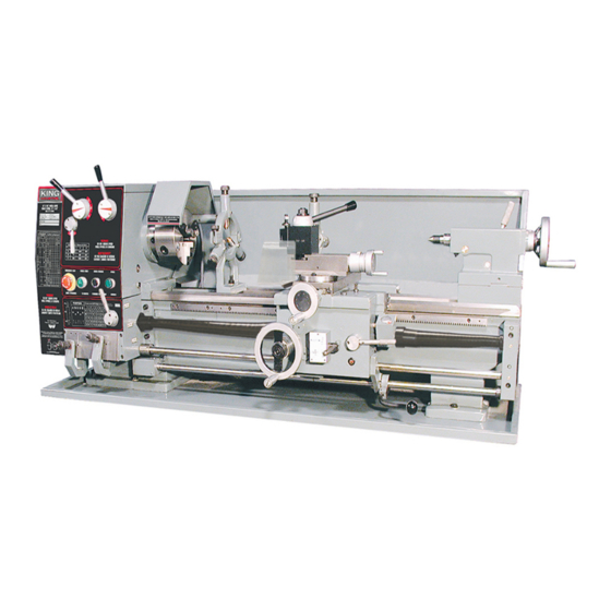
- Page 1 12” X 36” GEARHEAD METAL LATHE MODEL: KC-1236ML INSTRUCTION MANUAL COPYRIGHT © 2003 ALL RIGHTS RESERVED BY KING CANADA TOOLS INC.
- Page 2 IMPORTANT INFORMATION 2 2 - - Y Y E E A A R R K K I I N N G G C C A A N N A A D D A A T T O O O O L L S S LIMITED WARRANTY OFFERS A 2-YEAR LIMITED WARRANTY FOR THIS 12”...
-
Page 3: General Safety Instructions For Power Tools
GENERAL SAFETY INSTRUCTIONS FOR POWER TOOLS 1. KNOW YOUR TOOL 12. ALWAYS WEAR SAFETY GLASSES. Read and understand the owners manual and labels affixed to Always wear safety glasses (ANSI Z87.1). Everyday the tool. Learn its application and limitations as well as its eyeglasses only have impact resistant lenses, they are NOT specific potential hazards. - Page 4 ELECTRICAL & TECHNICAL INFORMATION ELECTRICAL INFORMATION WARNING! ALL ELECTRICAL CONNECTIONS MUST BE DONE BY A QUALIFIED ELECTRICIAN. FAILURE TO COMPLY MAY RESULT IN SERIOUS INJURY! ALL ADJUSTMENTS OR REPAIRS MUST BE DONE WITH THE METAL LATHE DISCONNECTED FROM THE POWER SOURCE. FAILURE TO COMPLY MAY RESULT IN SERIOUS INJURY! POWER SUPPLY WARNING:...
- Page 5 CLEANING, TEST RUN, GETTING TO KNOW YOUR LATHE Before operating this metal lathe, read this instruction manual and Make sure that all lubrication points and oil levels have been familiarize yourself with the required adjustments, operation inspected before putting your metal lathe into operation. See procedures, maintenance and lubrication.
-
Page 6: Operating Levers
OPERATING LEVERS Metal Lathe Operating Levers (Fig.2) feed. This lever has a safety interlock to prevent accidental engagement of the half nuts when the lathe is in feed mode. There Headstock Levers are 3 positions; the upper position engages the power longitudinal feed, the lower position engages the power cross feed and the •Levers 1 &... - Page 7 METAL LATHE CHARTS Metal Lathe Charts Below are all the charts which are found on the metal lathe plates. We have included these charts in this manual for reference purposes, in case one or many plates have been damaged and are no longer readable. FIGURE 3- Feed Rate Chart FIGURE 4- 9 Step Spindle Speed Chart FIGURE 6- Inch Thread Pitch Chart...
- Page 8 ADJUSTMENTS & OPERATION Mounting or removing chuck or face plate Before mounting a chuck, face plate or other attachments (A) Fig.8, it is very important that the mounting surfaces on both the spindle nose (B) and the attachment are extremely clean. All the camlocks (C) should be in their release position (camlock mark line matches the spindle nose mark line) and the cap screws (D) must be loos- ened before mounting.
- Page 9 ADJUSTMENTS & OPERATION Tailstock Adjustments & Operation The tailstock can be moved freely on the bedway and fastened at any position by locking tailstock lever (A) Fig.11. The tailstock quill can be moved in and out by using handwheel (B) and then fastened in place using quill locking lever (C).
- Page 10 ADJUSTMENTS & OPERATION Feed and Thread Selection To set the desired feed rate and thread selection, look at the charts in Fig’s.3 & 6 and determine the feed rate desired in relation to the thread to be cut. Once you have determined the job at hand, place the shifter levers (A &...
- Page 11 LIST OF MAIN GEARS, LEADSCREWS AND NUTS Headstock Gears Apron Gears, Screws, Nuts Gear Box Gears Description No. of Teeth Description No. of Teeth Description No. of Teeth Gear Gear Paired Rack Gear Gear Leadscrew Single thread Gear 51 (47) Paired Half Nuts Single thread...
- Page 12 LIST OF BEARINGS Bearings List Location Headstock Headstock Headstock Headstock Gear Box Headstock Headstock Gear Box Carriage Tailstock Carriage Change Gear FIGURE 19...
-
Page 13: Lubrication Points
LUBRICATION POINTS Before operating the metal lathe, check the oil level and lubricate all sliding surfaces such as the dovetail slot, half nut, worm gear, leadscrew, feed rod, handle rod, tailstock quill before and after operating. Follow the main lubrication points illustrated below. Lubrication Notes Note: Headstock lubrication point (1).
Need help?
Do you have a question about the KC-1236ML and is the answer not in the manual?
Questions and answers