
Related Manuals for King Industrial KC-1440ML


Summary of Contents for King Industrial KC-1440ML
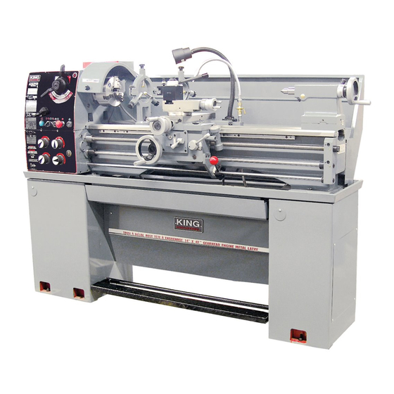
- Page 1 14” X 40” GEARHEAD METAL LATHE MODEL: KC-1440ML INSTRUCTION MANUAL COPYRIGHT © 2003 ALL RIGHTS RESERVED BY KING CANADA TOOLS INC.
-
Page 2: Limited Warranty
IMPORTANT INFORMATION 2 2 - - Y Y E E A A R R K K I I N N G G C C A A N N A A D D A A T T O O O O L L S S LIMITED WARRANTY OFFERS A 2-YEAR LIMITED WARRANTY FOR THIS 14”... -
Page 3: General Safety Instructions For Power Tools
GENERAL SAFETY INSTRUCTIONS FOR POWER TOOLS 1. KNOW YOUR TOOL 12. ALWAYS WEAR SAFETY GLASSES. Read and understand the owners manual and labels affixed to Always wear safety glasses (ANSI Z87.1). Everyday the tool. Learn its application and limitations as well as its eyeglasses only have impact resistant lenses, they are NOT specific potential hazards. -
Page 4: Electrical Information
THIS METAL LATHE MUST BE GROUNDED. IF NOT PROPERLY GROUNDED, THIS METAL LATHE CAN CAUSE ELECTRICAL SHOCK, PARTICULARLY WHEN USED IN DAMP LOCATIONS. TO AVOID SHOCK OR FIRE, IF THE POWER CORD IS WORN OR DAMAGED IN ANY WAY, HAVE IT REPLACED IMMEDIATELY. TECHNICAL INFORMATION KC-1440ML Main Specifications Max. swing over bed ..................................14” (355mm) Max. - Page 5 CLEANING, TEST RUN, GETTING TO KNOW YOUR LATHE Before operating this metal lathe, read this instruction manual and Make sure that all lubrication points and oil levels have been familiarize yourself with the required adjustments, operation inspected before putting your metal lathe into operation. See procedures, maintenance and lubrication.
-
Page 6: Operating Levers
OPERATING LEVERS Metal Lathe Operating Levers (Fig.2) are 3 positions; the upper position engages the power longitudinal feed, the lower position engages the power cross feed and the Headstock Levers center position is the disengaged position. • The thread lever 12 is used to engage the half nuts when threading. •Lever 1 is the H/L speed selector, this lever allows you to set the •... - Page 7 METAL LATHE CHARTS Metal Lathe Charts Below are all the charts which are found on the metal lathe plates. We have included these charts in this manual for reference purposes, in case one or many plates have been damaged and are no longer readable. FIGURE 6- 8 Step Spindle Speed Chart FIGURE 3- Inch Thread Pitch Chart FIGURE 7- Thread Dial Indicator Chart...
- Page 8 ADJUSTMENTS & OPERATION Mounting or removing chuck or face plate Before mounting a chuck, face plate or other attachments (A) Fig.8, it is very important that the mounting surfaces on both the spindle nose (B) and the attachment are extremely clean. All the camlocks (C) should be in their release position (camlock mark line matches the spindle nose mark line) and the cap screws (D) must be loos- ened before mounting.
- Page 9 ADJUSTMENTS & OPERATION Tailstock Adjustments & Operation The tailstock can be moved freely on the bedway and fastened at any position by locking tailstock lever (A) Fig.11. The tailstock quill can be moved in and out by using handwheel (B) and then fastened in place using quill locking lever (C).
- Page 10 ADJUSTMENTS & OPERATION Feed and Thread Selection To set the desired feed rate and thread selection, it may be necessary to change the gear configuration, refer to charts in Fig’s.3, 4, 5A & 5B. 36 feed speeds are possible in either the longitudinal or cross direction Fig. 5A.
- Page 11 COOLANT SYSTEM & LUBRICATION POINTS Using the Coolant System Lubrication Points It is suggested to use the coolant system during operations involving Before operating the metal lathe, check the oil level and lubricate all high speed cutting. Excessive heat and damage to your cutting tool will sliding surfaces such as the dovetail slot, half nut, worm gear, be avoided if the coolant system is on with the spout directed towards leadscrew, feed rod, handle rod, tailstock quill before and after...
Need help?
Do you have a question about the KC-1440ML and is the answer not in the manual?
Questions and answers