Table of Contents
Advertisement
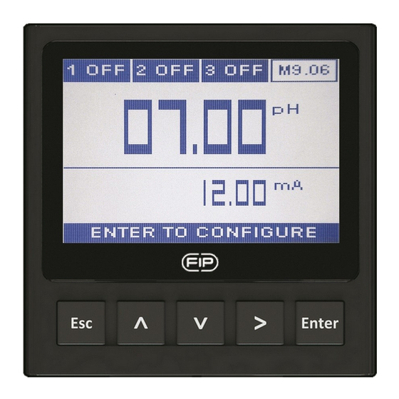
FLS M9.06
PH/ORP MONITOR
saFety instructions
General Statements
• Do not install and service the product without following the Instruction
Manual.
• This item is designed to be connected to other instruments which can be
hazardous if used improperly. Read and follow all associated instrument
manuals before using with it.
• Product installation and wiring connections should only be performed by
qualifi ed staff.
• Do not modify product construction.
Installation and Commissioning Statements
• Remove power to the instrument before wiring input and output connections.
• Do not exceed maximum specifi cations using the instrument.
• To clean the unit, use only chemical compatible products.
pacKinG List
Please verify that the product is complete and without any damage.
The following items must be included:
• M9.06 pH/ORP Monitor & Transmitter
• Instruction Manual for M9.06 pH/ORP Monitor & Transmitter
1
Advertisement
Table of Contents

Related Manuals for FIP FLS M9.06

Summary of Contents for FIP FLS M9.06
- Page 1 FLS M9.06 PH/ORP MONITOR saFety instructions General Statements • Do not install and service the product without following the Instruction Manual. • This item is designed to be connected to other instruments which can be hazardous if used improperly. Read and follow all associated instrument manuals before using with it.
-
Page 2: Technical Data
Description The new FLS F9.06 is a powerful pH/ORP monitor designed to satisfy a broad range of applications. A 4” wide full graphic display shows measured values clearly together with many other useful information. Moreover, due to the multicolor bright backlight, measurement status can be determined easily also from very long distance. -
Page 3: Standards And Approvals
Electrical • Supply Voltage: 12 to 24 VDC ± 10% regulated • 2 x Current output: - 4-20 mA, isolated, fully adjustable and reversible - Max loop impedance: 800 Ω @ 24 VDC - 250 Ω @ 12 VDC • 2 x Solid State Relay output: - User selectable as ON-OFF, proportional frequency, proportional pulse, timed pulse - Optically isolated, 50 mA MAX sink, 24 VDC MAX pull-up voltage... -
Page 4: Panel Mounting
Dimensions paneL mountinG WaLL mountinG instaLLation Mechanical installation The pH/ORP monitor & transmitter is available just in one packaging for panel or wall installation. The panel version is installed using the panel mounting kit (M9.SN1), while the wall mounting version is got fixing the panel mounting version on the wall mounting kit (M9.KWX). -
Page 5: Panel Installation
Panel installation Fix instrument on the panel rotating by hand the fixing snails (M9.SN1). Wall installation Use the panel mounting kit (M9.SN1) to fix the M9.06 on the dedicated frontal cutout of the wall mounting kit (M9.KWX). Tighten front screws of box and waterproof connectors of cables, internally mount caps on screw sites to get a IP65 watertight installation. -
Page 6: General Recommendation
WirinG General recommendation Always ensure the power supply is switched off before working on the device. Make wiring connections according to wiring diagrams. • Terminals accept 26 to 12 AWG (0.08 to 2.5 mm2) • Strip around 10 mm (0.4”) of insulation from the wire tips and tin bare ends to avoid fraying. -
Page 7: Probe Wiring Diagram
Refer to dedicated sensor manual for its wiring. In case a temperature sensor (Pt100-Pt1000) is not available, place a brigde connection between 28 - 29 and between 29 - 30. poWer/Loop WirinG DiaGram Stand-alone application, Connection to a PLC with built-in no current loop used power supply Power Supply... - Page 8 PT100 - PT1000 PT100 - PT1000 two wires connection three wires connection REF pH REF pH PT100/1000 PT100/1000 Pt100 - Pt1000 no connection PT100/1000 soLiD-state reLay WirinG DiaGram (For ssr1 anD ssr2) Connection to a PLC with NPN input Connection to a PLC with PNP input Internal PLC Internal PLC connection...
- Page 9 Connection to an User User N.O. User AC or DC N.O. N.O. AC or DC AC or DC AC or DC Power Power Power Power User User Imax = 50mA Imax = 50mA Imax = 50mA Imax = 50 lmax = 50mA lmax = 50mA The alarm is off during normal operation and goes ON according to...
-
Page 10: Operational Overview
operationaL menu Directory oVerVieW The M9.06 pH/ORP monitor and Settings transmitter features a full graphic display and a five-button keypad for system set-up, calibration and operation. Full graphic display has a white backlight during standard conditions, a green backlight in case a external device control is Calibration activated (ON/OFF, PROPORTIONAL... - Page 11 menu LeVeL Probe Unit Temperature Unit Manual Temperature pH/ORP Probe Calibration Temperature Probe Calibration 1 SSR 2 SSR 3 RELAY 4 RELAY eDit LeVeL Output Test pusH Button 4-20mA1 4-20mA2 Language to modify an item Filter Backlight Password Default Data to scroll right Output Assigment Hold...
-
Page 12: Output Mode
output moDe The M9.06 pH/ORP monitor and transmitter features 2 solid state relays and 2 mechanical relays in addition to 2 analog output 4-20mA. Only the second mechanical relay can be set as an alarm (icon is 4ALR) related to the feedback of external device managing. Icon will turn to 4OTA (Over Time Alarm) in case the setpoint has not been reached within set maximum timing. - Page 13 Digital outputs can be set in the following way: ON-OFF MODE (icon reports O-F) ON-OFF MODE (icon reports O-F) alkaline dosing acid dosing Hysteresis Setpoint Hysteresis Output relaxed Time Output relaxed Time Output energized Output energized PROPORTIONAL MODE (icon PROPORTIONAL MODE (icon reports PRP) alkaline dosing reports PRP) acid dosing Prop.
-
Page 14: Ordering Data
orDerinG Data Description power Wire power sensor part no. output /name supply technology input Panel mount 2*(4-20mA), M9.06.P1 pH/ORP 12 - 24 VDC 3/4 wire pH/ORP 2*(S.S.R.), monitor 2*(mech. relay) Wall mount 2*(4-20mA), M9.06.W1 pH/ORP 12 - 24 VDC 3/4 wire pH/ORP 2*(S.S.R.), monitor... - Page 15 note...
- Page 16 Fip - Formatura iniezione polimeri s.p.a. Loc. Pian di Parata 16015 Casella Genova - Italy Tel. +39 010 96211 Fax +39 010 9621209 www.flsnet.it...
Need help?
Do you have a question about the FLS M9.06 and is the answer not in the manual?
Questions and answers