Table of Contents
Advertisement
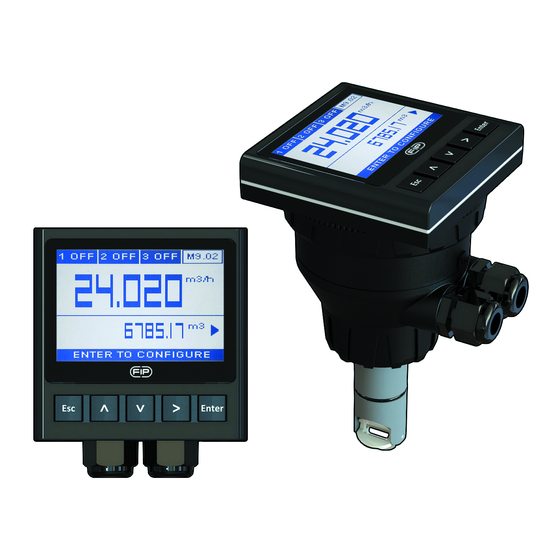
FLS M9.02
FLOW MONITOR & TRANSMITTER
SAFETY INSTRUCTIONS
General Statements
• Do not install and service the product without following the Instruction
Manual.
• This item is designed to be connected to other instruments which can be
hazardous if used improperly. Read and follow all associated instrument
manuals before using with it.
• Product installation and wiring connections should only be performed by
qualified staff.
• Do not modify product construction.
Installation and Commissioning Statements
• Remove power to the instrument before wiring input and output connections.
• Do not exceed maximum specifications using the instrument.
• To clean the unit, use only chemical compatible products.
PACKING LIST
Please verify that the product is complete and without any damage.
The following items must be included:
• M9.02 Flow Monitor
• Instruction Manual for M9.02 Flow Monitor
• Instruction Manual for F3.00 Flow Sensor (only for M9.02.XX Field Mount
Flow Monitor).
1
Advertisement
Table of Contents

Related Manuals for FIP FLS M9.02

Summary of Contents for FIP FLS M9.02
-
Page 1: Safety Instructions
FLS M9.02 FLOW MONITOR & TRANSMITTER SAFETY INSTRUCTIONS General Statements • Do not install and service the product without following the Instruction Manual. • This item is designed to be connected to other instruments which can be hazardous if used improperly. Read and follow all associated instrument manuals before using with it. -
Page 2: Technical Data
DESCRIPTION The new FLS M9.02 is a powerful flow monitor designed to convert the frequency signal of FLS flow sensors into a flow rate. M9.02 is equipped with a wide full graphic display 4” which shows measured values clearly and a lot of other useful information. - Page 3 Electrical • Supply Voltage: 12 to 24 VDC ± 10% regulated • FLS hall effect flow Sensor power: - 5 VDC @ < 20 mA - Optically isolated from current loop - Short circuit protected • 1 x Current output: - 4-20 mA, isolated, fully adjustable and reversible - Max loop impedance: 800 Ω...
-
Page 4: Compact Mounting
DIMENSIONS COMPACT MOUNTING PANEL MOUNTING WALL MOUNTING... - Page 5 Mechanical installation The flow monitor & transmitter is available just in one packaging for compact field version, panel or wall installation. The compact field version is mounted on top of the sensor using the compact mounting kit (F6.KC1), the panel version is installed using the panel mounting kit (M9.LN1), while the wall mounting version is got fixing the panel mounting version on the wall mounting kit (M9.KWX).
- Page 6 Compact installation The compact mounting kit (F6.KC1) includes the compact plastic adapter with gasket for IP65 watertight installation, sensor gasket, the compact cap and the locking ring. • Lubricate the sensor gasket with silicone lubricant and mount it on the proper seat.
- Page 7 Compact or Wall Installation Pull the electrical cables through liquid tight connectors. Use electrical cables with the proper external diameter for the liquid tight connector. PG11/PG9: external diameter between 2-7 mm (0.079-0.276”) REAR TERMINAL VIEW Refer to dedicated sensor manual for its wiring. POWER/LOOP WIRING DIAGRAM Stand-alone application, Connection to a PLC with built-in...
- Page 8 Connection to a PLC / Instrument with TWO separate power supplies wer Supply Power Supply PLC / Instrument + VDC PLC / Instrument 24 VDC + LOOP 12 - 24 VDC 4 - 20mA Loop Input 4 - 20mA Loop Input 24 VDC - LOOP 4 - 20mA Loop Input...
- Page 9 Connection to an User Imax External Relay N.C. N.O. Imax N.O. V= 12-24 VAC/VDC Imax = 50 mA The alarm is off during normal operation and goes ON according to Relay setting. If Imax > 50 mA use external Relay Connection to other FLS Instruments FLS monitor terminals...
-
Page 10: Operational Overview
OPERATIONAL MENU DIRECTORY OVERVIEW The M9.02 flow monitor and transmitter Settings features a full graphic display and a five-button keypad for system set-up, calibration and operation. Full graphic display has a white backlight during standard conditions, a red backlight in case a set alarm is activated (MAX, MIN, WINDOW MODE;... - Page 11 MENU LEVEL Installation Data Flow Unit Volume Unit Correction Factor Auto Calibration 1 SSR 2 SSR 3 RELAY 4 - 20 mA EDIT LEVEL Test Output PUSH BUTTON Language Filter Backlight to modify an item Flow Rate Decimal Point Password Asec Bi-Directional to scroll right...
-
Page 12: Output Mode
OUTPUT MODE The M9.02 flow monitor and transmitter features 2 solid state relays and 1 mechanical relay in addition to an analog output 4-20mA. PROCEDURE FOR OUTPUTS SETTING - go to the “Options” menu - enter into the “Outputs activation” sub menu - enable output(s) - go to the “Outputs”... - Page 13 Digital outputs can be set in the following way: MIN MODE (icon reports MIN) MAX MODE (icon reports MAX) Flow Flow Hysteresis Setpoint Setpoint Hysteresis Output relaxed Time Time Output relaxed Output energized Output energized WINDOW MODE (icon reports WDW) PULSE MODE (icon reports PLS) Flow Setpoint...
-
Page 14: Ordering Data
ORDERING DATA Description Power Wire power Sensor Part No. Output /Name supply Technology Input 1*(4-20mA), Flow M9.02 Flow Monitor 12 - 24 VDC 3/4 wire 2*(S.S.R.), (Frequency) 1*(mech. relay) 1*(4-20mA), Panel mount Flow M9.02.P1 12 - 24 VDC 3/4 wire 2*(S.S.R.), Flow Monitor (Frequency) - Page 15 Description Power Wire power Sensor Part No. Output /Name supply Technology Input 1*(4-20mA), Field mount Flow M9.02.07 12 - 24 VDC 3/4 wire 2*(S.S.R.), Flow Monitor (Frequency) 1*(mech. relay) 1*(4-20mA), Field mount Flow M9.02.08 12 - 24 VDC 3/4 wire 2*(S.S.R.), Flow Monitor (Frequency)
-
Page 16: Spare Parts
ACCESSORIES Part No. Name Description Plastic adapter with compact cap and locking nut F6.KC1 Compact mounting kit (for M9.02 only) 144x144mm plastic box for wall installation of all panel M9.KW1 Wall mounting kit mount monitors Wall mounting kit with 144x144mm plastic box and 110/230VAC to 24 VDC power M9.KW2 power supply supply for wall installation of all panel mount monitors...
Need help?
Do you have a question about the FLS M9.02 and is the answer not in the manual?
Questions and answers