Sign In
Upload
Download
Table of Contents
Contents
Add to my manuals
Delete from my manuals
Share
URL of this page:
HTML Link:
Bookmark this page
Add
Manual will be automatically added to "My Manuals"
Print this page
×
Bookmark added
×
Added to my manuals
Manuals
Brands
ABB Manuals
Measuring Instruments
10D1476
Instruction manual
ABB K-MAG 10D1476 Instruction Manual
Magnetic flowmeters
Hide thumbs
Also See for K-MAG 10D1476
:
Installation instructions manual
(10 pages)
1
2
Table Of Contents
3
4
5
6
7
8
9
10
11
12
13
14
15
16
17
18
19
20
21
22
23
24
25
26
27
28
29
30
31
32
33
34
35
36
37
38
39
40
41
42
43
44
45
46
47
48
49
50
51
52
53
54
55
page
of
55
Go
/
55
Contents
Table of Contents
Bookmarks
Table of Contents
Table of Contents
Safety Summary
Read First
Introduction
General
Model Number Breakdown
Specifications
Installation
Inspection
Location
Mounting
Meter Orientation
Meter Handling
Pipe Connections
Basic Mounting Procedure, Standard Coupling
MM (1/25 - 1-1/2 Inch) Meter Sizes
100 MM (2 - 4 Inch) Meter Sizes
Mounting Procedure, Sanitary Coupling
Grounding Procedure
General
Conductive Pipeline
Non-Conductive or Insulated Pipeline
Electrical Interconnection
START-UP and OPERATION
Functional Description
Basic Operating Principle
Signal Voltage Generation
Magnet Coil Drive Circuits
Volumetric Flow Rate Measurement
Operating Characteristics
Liquid Variables
Liquid Conductivity
Liquid Temperature
Other Liquid Variables
Metering Characteristics
Circuit Description
Primary Signals
Constant Meter Factor (CMF) PC Assembly
Advertisement
Quick Links
1
Table of Contents
2
Model Number Breakdown
3
Specifications
4
Installation
5
Electrical Interconnection
6
Start-Up and Operation
Download this manual
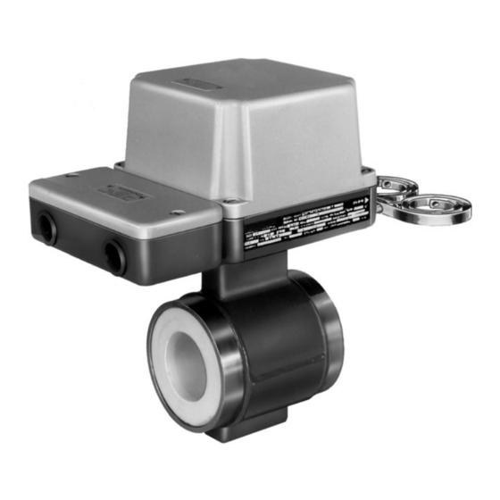
INSTRUCTION MANUAL
MAGNETIC FLOWMETERS
10D1476 Design Level S
1/25 - 4 in.
K-MAG
MAGNETIC FLOWMETER
PN25009A
Table of
Contents
Previous
Page
Next
Page
1
2
3
4
5
Advertisement
Table of Contents
Need help?
Do you have a question about the K-MAG 10D1476 and is the answer not in the manual?
Ask a question
Questions and answers
Related Manuals for ABB K-MAG 10D1476
Measuring Instruments ABB 10D1475 Installation Instructions Manual
Magnetic flowmeter (10 pages)
Measuring Instruments ABB COPA-XM 3000 Series Instruction Manual
Magnetic flowmeter (72 pages)
Measuring Instruments ABB MAG-X 3000 Series Instruction Manual
Magnetic flowmeters (58 pages)
Measuring Instruments ABB MINI-MAG 10D1475 Series Instruction Manual
Magnetic flowmeters (57 pages)
Measuring Instruments ABB CK-MAG 10D1477 Instruction Manual
Magnetic flowmeter (52 pages)
Measuring Instruments ABB MINI-MAG 10D1475 Instruction Manual
Magnetic flowmeter (52 pages)
Measuring Instruments ABB FXE4000 Commissioning Instructions
Copa-xe/mag-xe electromagnetic flowmeter (36 pages)
Measuring Instruments ABB COMMANDER 1911 Operating Manual
Circular chart recorders. controller versions (44 pages)
Measuring Instruments ABB K-MAG 10DX4311 Instruction Manual
Magnetic flowmeters (55 pages)
Measuring Instruments ABB 10DX3111G Instruction Manual
Magnetic flowmeter sizes 30" through 78" (44 pages)
Measuring Instruments ABB 3000 Series Instruction Manual
Ac magnetic flowmeters design level a sizes 14 through 24 inches (38 pages)
Measuring Instruments ABB Advance Optima Caldos 15-Ex Operator's Manual
Category 2g analyzer modules (44 pages)
Measuring Instruments ABB RATOSIGHT 10A2235 Instruction Manual
Variable area flowmeters (5 pages)
Measuring Instruments ABB ReliaMod RMM B 4R Installation And Maintenance Instructions Manual
Modular metering (30 pages)
Measuring Instruments ABB V/A MASTER 10A4500 Operating Instruction Manual With Parts List
(51 pages)
Measuring Instruments ABB RES670 Product Manual
Relion 670 series phasor measurement unit (111 pages)
This manual is also suitable for:
K-mag 10d1418
K-mag 10d1419
K-mag 10d1430
K-mag 10d1435
K-mag 10d1462
K-mag 10d1465
...
Show all
K-mag 10d1472
K-mag 10d1475
K-mag 10d1477
K-mag 10ds1111
K-mag 10dx2112
K-mag 10dx3011
K-mag 10dx3111
K-mag 10dx3119
K-mag 10dx3121
K-mag 10dx3311
K-mag 10dx4311
K-mag dm21
K-mag ds21
K-mag dt43
K-mag fxe4000
K-mag fxf2000
K-mag fxt4000
Table of Contents
Print
Rename the bookmark
Delete bookmark?
Delete from my manuals?
Login
Sign In
OR
Sign in with Facebook
Sign in with Google
Upload manual
Upload from disk
Upload from URL


Need help?
Do you have a question about the K-MAG 10D1476 and is the answer not in the manual?
Questions and answers