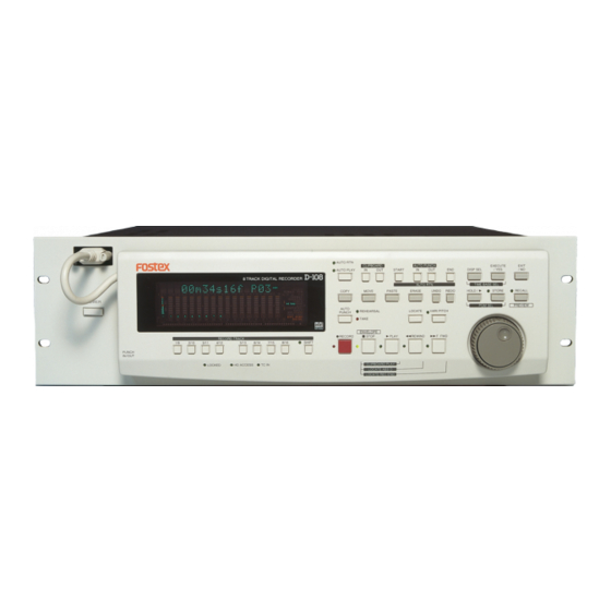
Fostex D-108 Service Manual
Digital multitrack recorder
Hide thumbs
Also See for D-108:
- Owner's manual (141 pages) ,
- Quick operation manual (28 pages) ,
- Supplement owner's manual (2 pages)
Advertisement
Quick Links
Advertisement

Related Manuals for Fostex D-108


Summary of Contents for Fostex D-108
- Page 1 Service Manual Model D-108 & 8345/5040 DIGITAL MULTITRACK RECORDER...
- Page 2 CAUTION: CAUTION TO PREVENT ELECTRIC SHOCK, MATCH RISK OF ELECTRIC SHOCK WIDE BLADE OF PLUG TO WIDE SLOT, DO NOT OPEN FULLY INSERT. ATTENTION: CAUTION: TO REDUCE THE RISK OF ELECTRIC SHOCK, POUR ÉVITER LES CHOCS ÉLECTRIQUES, DO NOT REMOVE COVER (OR BACK). INTRODUIRE LA LAME LA PLUS LARGE DE NO USER-SERVICEABLE PARTS INSIDE.
-
Page 3: Table Of Contents
Service mode, error code list, exploded view, PCB assembly, parts list and circuit diagrams are given in this manual to assist the service technician in maintaining the Model D-108. The following accessories are supplied with D-108 as the standard accessories. -
Page 4: Specifications
D-108 1. SPECIFICATIONS D-108 INPUT & OUTPUT INPUT (1 ~ 8) Connector RCA pin jack (x 8) Input Level -10 dBV Input Impedance 10 kΩ or more OUTPUT (1 ~ 8) Connector RCA pin jack (x 8) Output Level -10 dBV Load Impedance 10 kΩ... - Page 5 D-108 OPERATION (continued) Digital Scrubbing (JOG) 0 ~ 1 times (Envelope can be displayed when selecting only one track.) Locate Memory 6 (7 including [LOCATE] key temporary memory) + 99 LEVEL INDICATION Type FL Bargraph Number of Indicated Levels 11 dots (-∞, -42, -30, -24, -18, -12, -9, -6, -3, 0, OVER)
- Page 6 TTL level 75 Ω (ON / OFF by terminator SW) Load Impedance DIMENSIONS 215 (W) x 80 (D) mm POWER SUPPLY Supplied from D-108 Digital DC + 5 V Analog DC + 19 V / - 15 V 5040 INPUT (1 ~ 8)
-
Page 7: Controls, Indicators & Connectors
D-108 2. CONTROLS, INDICATORS & CONNECTORS < Front Panel Section with Detachable Controller > AUTO RTN CLIPBOARD AUTO PUNCH EXECUTE EXIT AUTO PLAY START DISP SEL /YES D-108 8TRACK DIGITAL RECORDER TIME BASE SEL AUTO RTN COPY MOVE PASTE ERASE... - Page 8 D-108 < Front Panel Section without Detachable Controller > D-108 8TRACK DIGITAL RECORDER POWER 1. Detachable remote controller connector (DSUB 15-pin) 5. Hard disk power LED (Green) 2. Power switch [ POWER ] 6. Removable hard disk cartridge slot 3. Controller mount 7.
- Page 9 D-108 32. Copy key [ COPY ] 38. Rewind button [ REWIND ] 33. Auto punch mode on / off key 39. Fast forward button [ F FWD ] [ AUTO PUNCH ( REHEARSAL/TAKE )] 40. Locked LED [ LED ] (Green) 34.
-
Page 10: Software Update
8. Flash ROM” (page 21). The SCSI ID to be connected to the D-108 must be selected to 0 ~ 5. The SCSI ID “6” is used for backing up purpose exclusively. The SCSI ID “7” cannot be used on the D-108 by technical reasons. -
Page 11: Service Mode
D-108 4. SERVICE MODE There are various optional modes available in the D-108 Service Mode. Please utilize them when servicing the unit. 4-1. Putting D-108 into Service Mode The way of putting the D-108 into Service Mode is as follow. - Page 12 44.1kHz If the D-108 is in a normal condition, “44.1kHz” and “DIGITAL” will be lit solid. The odd (1, 3, 5, 7 and L) and even (2, 4, 6, 8 and R) channels indicate the left and right input level of S/P DIF digital signal fed to the DATA INPUT jack respectively.
- Page 13 44.1kHz If the D-108 is in a normal condition, all the segments on the FL display will be lit solid (Dot matrix and bargraph meter sections on the FL display will blink.) and all the LEDs on the top panel will start blinking.
- Page 14 ANALOG IN ANALOG OUT MIDI DATA SCSI OPTICAL AC IN INPUT OUTPUT INPUT OUTPUT THRU External SCSI Device CAUTION: In order not to form a MIDI signal loop, connect the MIDI cable after putting the D-108 into the Service Mode.
- Page 15 In order to go back to the normal display, press the EXIT/NO key or STOP button. 4-5-1. SCSI Port Check If the D-108 does not recognize a SCSI device connected to the D-108 SCSI port, the prompt below will be displayed. 44.1kHz The following is considered to be the cause of problem.
- Page 16 D-108 In the case that the inserted disk is not FDMS-3 formatted, the following prompt will be displayed. 44.1kHz Fs, DIGITAL IN, DIGITAL OUT and SLAVE MODE settings on the disk to be used when the Self Check test is executed should be as follow.
- Page 17 D-108 Fs, DIGITAL IN, DIGITAL OUT and SLAVE MODE settings on the internal disk to be used when the Self Check test is executed should be as follow. • Fs: 44.1kHz • DIGITAL IN: OFF (L: - R: -) • DIGITAL OUT: ADAT •...
- Page 18 D-108 4-5-5. S/P DIF In/Out (44.1kHz) Check By connecting the DATA IN and OUT terminals, this tests checks if the S/P DIF signal output by itself is correctly received. If the PLL circuit is not in a “LOCKED” condition, the prompt below will be displayed.
- Page 19 4-5-8. D-108 Vari-Pitch Circuit (48kHz) Check Using the master clock generated through the D-108 vari-pitch circuit on the MAIN PCB, the adat digital signal is output. This test checks if the adat digital signal output by itself is correctly received. If not, it means that the vari-pitch circuit does not work correctly.
- Page 20 SETUP menu “Drive_Sel?” will be initialized. Up to 2 x SCSI drives can be connected to the D-108 at a time. One is for recording / reproducing (SCSI ID: 0 ~ 5) and the other for exclusive backing up (SCSI ID: 6). Initializing is possible on the SCSI drive (ID: 0 ~ 5) used for recording / reproducing only.
- Page 21 4-9. Free Block Check This mode is used to check the condition of the diskette inserted into an external SCSI drive connected to the D-108 or the internal E-IDE hard disk drive. The drive to be checked is the one currently selected drive by the SETUP menu “Drive_Sel?”.
-
Page 22: Error Code List
The chart below indicates the error code number and corresponding description. Since the error code list is basically designed for our engineers to improve the software, the description is quite technical. If you find the D-108 with one of the error codes displayed, we encourage you to update the software first. In case updating the software does not solve the problem, we would like you to inform us about details. -
Page 23: Model 8345/5040 Installing Procedures
6. MODEL 8345/5040 INSTALLING PROCEDURES CAUTION: When retrofitting both the MODEL 8345 and 5040 to the D-108, please make sure that the MODEL 5040 will be the one to retrofit first. Open up the top panel by loosening the following screws. - Page 24 • 4 x hex screws originally attached to the D-SUB connectors Connect the following cables. • 17-pin flat cable from the connector J13 on the D-108 MAIN PCB assy to the connector J4 on the MODEL 5040 PCB assy • 8-pin flat cable from the connector J14 on the D-108 MAIN PCB assy to the connector J5 on the MODEL 5040 PCB assy •...
- Page 25 • 4 x BBT 3 x 8 BZn screws included in the MODEL 8345 package - XLR connector section Connect the following cables. • 25-pin flat cable from the connector J9 on the D-108 MAIN PCB assy to the connector J1 on the MODEL 5040 PCB assy •...
-
Page 26: Exploded View, Pcb Assembly & Parts List
8221 2591 00 Chassis, D-108 8274 1690 00 PCB assy, Main, D-108 8207 0130 00 Foot, FF1011 8274 1710 00 PCB assy, Power Supply, D-108 8274 2020 00 PCB assy, Regulator, D-108 8221 2610 00 Bracket, AC IN, D-108 8274 1720 00 PCB assy, Connect, D-108... - Page 27 D-108 D-108 OVERALL EXPLODED VIEW BBT 3x8 BZn P 3x5 CZn B 3x6 BZn BBT 3x8 BZn P 3x5 CZn BBT 3x8 BZn B 3x6 CZn B 3x6 BBT 3x6 BZn BBT 3x8 BZn BBT 3x6 BPT 3x8 BZn BPT 3x8...
- Page 28 5351 5351 5351 5351 C166 C266 C366 C466 C256 C356 C456 C156 R252 R352 R452 R152 8254973 201 PCB. MAIN D-108 C904 U904 5040 2103 C913 C914 POWER J1001 L1002 SELF L1005 CHECK U905 U903 8251973 002 EPROM PCB. CONNECT.D-108...
- Page 29 • Foil Side of MAIN / CONNECT PCB R920 R919 R918 TP10 PCB. MAIN. D-108 J1001 D19 D18 D17 D16 D15 D14 W1002 W1001...
- Page 30 • Parts side of DISPLAY PCB DGND A.RTN CLIPBOARD AUTO PUNCH DISP SEL EXECU/YES EXIT/NO START W10 73 DGND DGND A.PLAY DGND SPACER SPACER RECALL UNDO PASTE MOVE ERASE HOLD STORE REDO COPY DGND AUTO PUNCH V.PITCH TAKE DGND 31 33 9/16 SHIFT DGND...
- Page 31 CAUTION : FOR CONTINUED PROTECTION AGAINST RISK OF FIRE. REPLACE ONLY WITH SAME TYPE FUSE. PRECAUTION : EN VUE DE LA PROTECTION CONTINUELLE CONTRE LES 8251974 302 RISQUES D’INCENDIE. REMPLACER AVEC LE MEME TYPE DE FUSIBLE. PCB. POWER SWITCH. D-108...
- Page 32 • Foil side of POWER / POWER SW / REGULATOR PCB PCB. POWER. D-108 8251974 301 DGND AGND PQ1CF2...
- Page 33 U014 8236 5701 01 ST, DG, driver, DTC114EK R012 8230 5001 01 ST, carbon, 1/10W, 100Ω, 5% U015 8236 0838 02 QFP, DG, CPU, main, FD-8/D-108, R013 8230 5003 31 ST, carbon, 1/10W, 330Ω, 5% mask, SH7042, F28 R014 8230 5001 05 ST, carbon, 1/10W, 1MΩ, 5%...
- Page 34 D-108 Ref. No. Part No. Description Ref. No. Part No. Description R052 8230 5001 01 ST, carbon, 1/10W, 100Ω, 5% R142~452 8230 5001 01 ST, carbon, 1/10W, 100Ω, 5% R053, 054 8230 5001 00 ST, carbon, 1/10W, 10Ω, 5% R156~856 8230 5001 01 ST, carbon, 1/10W, 100Ω, 5% R055, 056 8230 5005 61 ST, carbon, 1/10W, 560Ω, 5%...
- Page 35 D-108 Ref. No. Part No. Description Ref. No. Part No. Description C048 8232 1431 06 VT, ALU, 16V, 10µF, 20%, SME-VB C153~453 8232 1431 06 VT, ALU, 16V, 10µF, 20%, SME-VB C049~051 8233 5041 03 ST, CER, 25V, 0.01µF, 10%, CC20R C154~454 8233 5041 03 ST, CER, 25V, 0.01µF, 10%, CC20R...
- Page 36 8230 1381 03 HT, carbon, 1/4W, 10kΩ, 5% R066~068 8230 1381 54 HT, carbon, 1/4W, 150kΩ, 5% Ref. No. Part No. Description 8274 1700 00 PCB assy, Display, D-108 CAPACITORs B101 8251 5111 00 Plain PCB, Main, D-108 ALU = Electrolytic type CER = Ceramic type Ref.
- Page 37 Part No. Description R008 8230 1251 04 H, metal, 2W, 100kΩ, 5%, F20, RSS 8274 1730 00 PCB assy, Power SW, D-108 R009 8230 1386 89 HT, carbon, 1/4W, 6.8Ω, 5% B101 8251 9743 02 Plain PCB, Power SW, D-108 R010 8230 1381 03 HT, carbon, 1/4W, 10kΩ, 5%...
- Page 38 C016, 017 8232 8181 04 VT, CER, 25V, 0.1µF, +80-20%, YF Ref. No. Part No. Description C018, 019 8232 3542 22 VT, CER, 250V, 0.0022µF, 20%, 8274 2020 00 PCB assy, Regulator, D-108 ECK-ZNS B101 8251 9743 03 Plain PCB, Regulator, D-108 C020, 021 C022 8232 8031 03 VT, CER, 50V, 0.01µF, +80-20%, YF...
- Page 39 8345 PCB PATTERN DRAWING • Parts Side of 8345 PCB TC OUT TC IN VIDEO VIDEO THRU TC OUT WORD SN75124 HC04 SN75123 NJM2207 NJM592 TC9246 R43 TP3 HC04 C91 R65 28MHz TC9246 HC74 C78 R48 R49R59 R58 C68 U29 U28 NJM4580 C89 R61 C88R63 R64 C92 CLK GR...
- Page 40 5040 PCB PATTERN DRAWING • Parts Side of 5040 PCB TO MAIN BAL OUT 5040 1-8CH 5041 only 5041 9-16CH BAL IN BAL OUT 1-8CH 1-8CH 5040 & 5041 C812 C712 C612 C512 C412 C312 C212 C112 C1612 C1512 C1412 C1312 C1212 C1112...
- Page 41 D-108 8345 Parts List • 8345 PCB assy Ref. No. Part No. Description Ref. No. Part No. Description PCB assy, 8345 R005, 006 8230 5001 03 ST, carbon, 1/10W, 10kΩ, 5% B101 8251 9612 01 Plain PCB, 8345 R007 8230 5002 02 ST, carbon, 1/10W, 2kΩ, 5% R008 8230 5001 03 ST, carbon, 1/10W, 10kΩ, 5%...
- Page 42 D-108 Ref. No. Part No. Description Ref. No. Part No. Description R070 8230 5001 04 ST, carbon, 1/10W, 100kΩ, 5% C068 8233 5041 03 ST, CER, 25V, 0.01µF, 10%, CC20R R071 8230 5001 01 ST, carbon, 1/10W, 100Ω, 5% C069...
- Page 43 D-108 5040 Parts List • BALANCE I/O PCB assy Ref. No. Part No. Description CAPACITORs PCB assy, Balance I/O, 5040 ALU = Electrolytic type B101 8251 9581 00 Plain PCB, Balance I/O, 5040 CER = Ceramic type PES = Mylar type Ref.
- Page 44 D-108 MISCELLANEOUS Ref. No. Part No. Description J0001 8245 3120 05 Connector, PL, jack, D-SUB, 25P, 70057-025, EMIFIL J0002 8245 3120 05 Connector, PL, jack, D-SUB, 25P, 70057-025, EMIFIL J0003 J0004 8245 2720 17 Connector, PI, jack, FPC, 17P J0005...
-
Page 45: Circuit Diagrams
8. CIRCUIT DIAGRAMS ROOT, MAIN D-108 (1/11) AD-DA GATE ARRAY AD-DA AUDIO_IF AD_D[1..4] D[0..15] AD_D[1..4] AD_D[1..4] AD_D[1..4] AD_D[1..4] D[0..15] D[0..15] D[0..15] D[0..15] DA_D[1..4] A[0..18] DA_D[1..4] DA_D[1..4] DA_D[1..4] DA_D[1..4] A[0..18] A[0..18] A[0..18] A[0..18] LRCK LRCK LRCK LRCK LRCK BCK_ADDA BCK_ADDA BCK_ADDA... - Page 46 CPU, MAIN, D-108 (2/11) U12E 74HC14 C905 U904A 0.01 74HC04 DGND U904B 74HC04 R901 U904C POWER POWER_SEL OPTION /OP_IRQ 74HC04 C901 /422ON SELF CHECK 1.5K 470p U904D SELF_CHECK DGND 74HC04 VARI/EXT 0.01 DGND DGND DMA_SEL DGND SCSI_TMOUT /RST /RST DGND...
- Page 47 MEMORY, MAIN, D-108 (3/11) FLASH MEMORY DRAM D[0..15] D[0..15] A[0..18] A[0..18] I/O0 I/O15 I/O1 I/O14 I/O2 I/O13 I/O3 I/O12 I/O4 I/O11 I/O5 I/O10 I/O6 I/O9 I/O7 I/O8 /LCAS DQ10 LCAS /UCAS J10A DQ11 UCAS DQ12 ROM CARD /RST DQ13 D[0..15]...
- Page 48 GATE ARRAY, MAIN, D-108 (4/11) U34C C920 /CS_OP[1..4] U34B R922 OP_A[1..5] DGND OP_D[0..7] U34D R921 /OP_RST C921 OP_D0 OP_D1 0.01 0.01 OP_D2 U34A OP_D3 OP_D4 DGND DGND DGND DGND 74HC245 74HC541 0.01 OP_D5 OP_D6 U16A U16B OP_D7 /CS_OP1 DGND /CS_GA...
- Page 49 SCSI I/F, MAIN, D-108 (5/11) /ATA_RST DMARQ IORDY_I INTRQ 4.7K DD[0..17] ATAD4 R918 R919 R920 RA221/331 RA221/331 RA221/331 /ATA_RST DGND DGND DD10 DGND ATAD3 DD11 ATAD2 ATAD1 /REQ DD12 ATAD0 /ATN /MSG DD13 /C/D RESET /BSY /I/O TO IDE HD...
- Page 50 VCO, MAIN, D-108 (6/11) VCO+5 22uH PLL1_CONT DIF_GR 4.7k FCONT1 0.01 0.01 10/16 R39 10K ADAT FCONT VCO+5 TEST PIN VCOGND 13027 (CHIP R) LOCK 8.2K VDDA DIF_GR AMPI AMPO VSSA 0.47 DIF_GR MCK1 OPT_IN TC9246F 0.01 ADAT_IN ADAT_IN ADAT_IN 0.01...
- Page 51 FCONT, MAIN, D-108 (7/11) C926 0.01 0.01 DGND U35B U35A U37B DGND OPT_IN U37C U37D ADAT_IN 74HC86 C923 C928 C929 74HC86 74HC00 100p U38A 0.01 U39A 0.01 U23A 74HC00 74HC74 DGND DGND 74HC00 LOAD R924 FCONT2_2 74HC74 74HC74 74HC161 C925 DGND 0.01...
- Page 52 ROOT, AD-DA, MAIN, D-108 (8/11) ADDA_IN ADDA ADDA_OUT ADDA IN ADDA_DG ADDA_OUT AIN[1. . 8 ] AI N+ [1..8] AOUT+ [1..8] AOUT[1. . 8 ] AIN[1. . 8 ] AIN[1. . 8 ] AI N+ [1..8] AI N+ [1..8] AI N+ [1..8] AI N+ [1..8]...
- Page 53 ADDA IN, D-108 (9/11) +2dBv 5040 BAL_IN[1..8] BAL_IN[1..8] BAL_IN[1..8] UNBAL IN AIN[1..8] AIN[1..8] AIN[1..8] C103 C503 +2dBv G=-4.5dB G=-4.5dB 0.01 0.01 C101 C501 R101 R102 R104 R501 R502 R504 10/16 10/16 AIN1 AGND AIN5 AGND R108 R508 BAL_IN1 R103 BAL_IN5...
- Page 54 ADDA, MAIN, D-108 (10/11) AIN+[1..8] AIN+[1..8] AIN-[1..8] AIN+2 AIN-[1..8] AIN-2 DA_D[1..4] DA_D[1..4] AIN+1 AIN-1 RST_ADDA C155 D+5_1 /RST MSCK_ADDA C162 LRCK_ADDA 0.01 R161 U152 BCK_ADDA MSCK_AD ZMUTE DVDD C161 U151 C166 DVSS VREF 10/16 AGND AD_D[1..4] C153 C154 AINR+ AD_D[1..4]...
- Page 55 ANALOG OUT, MAIN, D-108 (11/11) AOUT+[1..8] AOUT+[1..8] AOUT+[1..8] A+15 A+15 C113 G=+2.08dB 0.01 C313 G=+2.08dB 0.01 U153A C116 NJM4565M U353A AGND C111 C516 NJM4565M AOUT+1 100/16 AGND C511 AOUT1 AOUT+5 100/16 10/16 AOUT5 R111 10/16 R113 R511 2.7K R513 R114 C115 2.7K...
- Page 56 ROOT, DISPLAY, D-108 / D-160 (1/5) FRNT\KEY.SCH FRNT\MPUKEY.SCH FS[2..27] DIG0 DIG1 DIG0 DIG1 DGND KEY.SCH LEDA[0..3] FRNT\LED.SCH LEDA[0..3] LEDK[0..4] LEDK[0..4] LEDA[0..3] FS[2..27] FS[2..27] LEDK[0..4] FD[6..15] FD[6..15] LED.SCH DGND FRNT\FL.SCH DGND FS[2..27] FD[6..15] SCK_FL SO_FL DGND CE_FL SCK_FL AC6.2A AC6.2A SO_FL AC6.2B...
- Page 57 MPUKEY, DISPLAY, D-108 / D-160 (2/5) LGR4609-7000 6HOLE 1.5K 1% 10/50 BEAD DIG1 A114ES 150K DGND 6HOLE AC6.2B DIG0 BEAD 0.01 DGND DGND AC6.2A A114ES 150K Vdisp 6HOLE 0.1/50 10/50 0.1/50 Vdisp SO_FL AC6.2A Vdisp CE_FL LEDK[0..4] AC6.2B SCK_FL VdispF LEDK[0..4]...
- Page 58 KEY, DISPLAY, D-108 / D-160 (3/5) DIG1 JOG/SHUTTLE DIG0 SHIFT REWIND A/P_IN FS10 FS19 FS19 A/P_OUT SR_8/16 F.FWD AUTO PUNCH COPY FS18 FS27 FS18 FS27 100K SR_7/15 UNDO AUTO PLAY PITCH 0.01 100K FS17 FS17 FS26 0.01 DGND REDO SR_6/14...
- Page 59 LED, DISPLAY, D-108 / D-160 (4/5) LEDA[0..3] LEDA[0..3] LEDK[0..4] LEDA0 LEDA1 LEDA2 LEDA3 LEDK[0..4] LED(GRN) LED(GRN) LED(RED) LED(GRN) AUTO RETURN REHEARSAL SHIFT LEDK0 LED(GRN) LED(RED) LED(GRN) LED(GRN) A.PLAY TAKE STOP MTC IN LEDK1 LED(GRN) LED(GRN) LED(GRN) LED(GRN) HD ACCESS STORE...
- Page 60 FL, DISPLAY, D-108 / D-160 (5/5) 0.1/50 R64,C19:REMOVE /RST2 DGND Vdisp 470p CE_FL DGND SCK_FL SO_FL AA8/G12 AA7/G13 AA6/G14 Vdisp Vdisp AA5/G15 AM10 AA4/G16 DGND DGND AM11 Vdisp AM12 AM13 DGND AM14 AM35 AM15 AM34 AM16 AM33 LC75710/1/2 FS[2..27] FS[2..27]...
- Page 61 POWER / POWER SW / REGULATOR, D-108 DGND Vout 180uH DGND D1NL40 on/off PQ1CF2 330u/50 +12V A+15 47/50 0.01 AGND AGND A-15 DGND 4.7K 2SA1606 0.01 to MAIN 6.8V D+12 -30V S2V60 DGND Vdisp DGND 8263-12P DC-DCTRANS AC5.6-1 AC5.6-1 4049...
- Page 62 CONNECT, D-108 L1001 W1001 L1002 BEAD AC6.2A J1001 AC6.2B L1003 BEAD VDISP DGND AC6.2A L1004 BEAD AC6.2B DGND VDISP L1005 BEAD DGND L1006 BEAD B.IN7P L1007 BEAD-MMZ L1008 BEAD-MMZ /RST_DISP /ATN1 L1009 BEAD-MMZ /ATN2 TXD1 L1010 BEAD-MMZ W1002 RXD1 /RST_DISP...
- Page 63 ROOT, 8345 (1/3) MAIN /OP_RST NEWCLKD OP_D0 OP_D1 78M05 OP_D2 0.01 10/16 0.01 1/50 OP_D3 POWER OP_D4 NEWCLOCK OP_D5 OP_D6 OP_D7 A+19 OP_A0 AGND OP_A1 A-15 OP_D[0..7] OP_A2 OP_D[0..7] OP_D[0..7] OP_A3 AGND DGND OP_A4 0.01 /OP_IRQ B-IN5P /OP_WR OP_A[0..4] /OP_RD OP_A[0..4] OP_A[0..4] 10/16...
- Page 64 MCLK, 8345 (2/3) OP_A[0..4] OP_A[0..4] CONNECT OP_D[0..7] OP_D[0..7] /OP_RD CONNECT /OP_WR CONNECT /OP_CS3 /OP_CS4 /OP_IRQ CONNECT /OP_RST 470p 0.01 470p DGND U14B DGND DGND 74HCU04 0.01 0.01 0.01 0.01 U14A TST4 TST4 LTCF_N LTCF TST3 LTCF TST3 74HCU04 V_FIN FRMP TST2 FRMP TST2...
- Page 65 TC I/O, 8345 (3/3) XLR-3-31 10/16 BEAD DAN202K DAN202K 100K AGND AGND 2.7K CONNECT CS_TCG CS_TCG DAN202K /OP_WR 10/16 /OP_RD TC IN U24C U24B 74HC04 74HC04 NJM311M BEAD 0.01 DAN202K 100K OP_D[0..7] OP_D[0..7] CONNECT OP_A[0..4] OP_D0 OP_A[0..4] EMPT OP_D1 FRCI OP_D2 FRCO OP_D3...
- Page 66 BALANCE I/O, ROOT, 5040 (1/3) BALANCE OUT BALANCE IN BALANCE IND (5040 & 5041) TO MAIN 9..16CH L802 N.C. (5040 & 5041) L801 HOT_IN8 HOT_IN8 HOT_IN8 BAL_IN8 BAL_IN8 COLD_IN8 BALANCE OUT 9..16CHD12D10 COLD_IN8 COLD_IN8 GNDI8 GNDI8 L702 GND_IN8 L1604 GND_IN8 GND_IN8 BAL_IN7 BAL_IN7...
- Page 67 BALANCE I/O, INPUT, 5040 (2/3) A+15 A+15 G=-5.8dB G=-5.8dB 0.01 0.01 R106 R506 5.6k 5.6k C102 C502 R104 C106 C104 R504 C506 C504 W101 W501 47/16 47/16 JUMPER JUMPER COLD_IN1 COLD_IN5 -10dBv -10dBv BAL_IN1 BAL_IN5 HOT_IN1 HOT_IN5 C105 C505 R103 R503 C101 4560...
- Page 68 BALANCE I/O, OUTPUT 9 - 16, 5040 (3/3) A+15 A+15 9..16CH 0.01 0.01 R1211 R1611 C1610 C1210 C1212 C1612 100p C1607 C1207 100p 220/10 220/10 R1608 R1208 47/16 47/16 3.3k 3.3k HOT_OUT16 HOT_OUT12 DTC314TK DTC314TK AOUT16+ R1615 AOUT12+ R1213 R1613 U1201A U1601A U1602...
- Page 69 D-108 <NOTE>...
- Page 70 FOSTEX CORPORATION 3-2-35 Musashino, Akishima, Tokyo, Japan 196-0021 FOSTEX CORPORATION OF AMERICA 15431 Blackburn Ave., Norwalk, CA 90650, U.S.A. © PRINTED IN JAPAN DEC 1998 8288777000...
Need help?
Do you have a question about the D-108 and is the answer not in the manual?
Questions and answers