
Subscribe to Our Youtube Channel
Related Manuals for Glentek SMB9675-1A-1-6889


Summary of Contents for Glentek SMB9675-1A-1-6889
- Page 1 INSTALLATION & OPERATION MANUAL Model SMB9675-1A-1-6889 FADAL REPLACEMENT SENSORED VECTOR DRIVE MANUAL#: 9675-1040-000 REVISION: (A) DATE: 30 August 2010...
-
Page 3: Table Of Contents
2.2.3 Installation………………………………...….. 2.3 Communicating with the Vector Drive………………..2.3.1 Serial Port……………………………….…….. 2.3.2 USB Port………………………………...……. CHAPTER THREE: INSTALLING THE GLENTEK VECTOR DRIVE INTO A FADAL VMC 3.1 Removing the old drive………………………….………. 3.2 Mechanical Installation…………………………….……. 3.3 Electrical Installation………………………………….…. 3.3.1 Power Terminal Block Connections……..…... -
Page 4: Overview
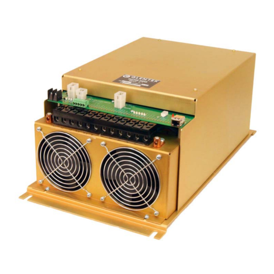
CHAPTER ONE: GENERAL 1.1. Overview The Glentek Inc. SMB9675-1A-1-6889 vector drive uses flux vector technology to close a torque (current) feedback loop. When applied to a three phase induction motor, the result is servo motor like performance from a standard three phase induction motor. -
Page 5: Chapter Two: Application Software
MotionMaestro© has many features that allow users to easily configure and tune the entire Glentek digital product line. However, for the Fadal VMC replacement vector drive most of the setup has been done at the factory. -
Page 6: Communicating With The Vector Drive
2.3. Communicating With The Vector Drive 2.3.1. Serial Port If your PC has a serial port (RS-232) you can connect to the vector drive with Glentek cable (GTK # GC2400-AL005AM-000). This cable has a female DB-9 (computer) on one end and an RJ-45 (vector drive) on the other. -
Page 7: Chapter Three
CHAPTER THREE: INSTALLING THE GLENTEK VECTOR DRIVE INTO A FADAL VMC 3.1. Removing the old drive Turn off the power to the VMC and wait 5 minutes before beginning removal. Disconnect all the wires and cables. If any wires are not labeled take note of their location. - Page 8 Before and after photos of a typical installation...
-
Page 9: Chapter Four: Setup And Tuning
CHAPTER FOUR: SETUP AND TUNING 4.1. Turning the Power On. Carefully recheck the wiring. Restore power to the VMC. After the VMC is finished initializing, check the vector drive status 7 segment display. One segment may be lighted or if the spindle is rotating slowly you will see a rotating pattern of segments lighting. -
Page 10: Motor Parameters
4.3. Motor Parameters From the Setup menu drop down, open the Induction Motor Vector Control dialog box as seen below. Motor Parameters Section; In the working column enter the Stator Resistance (phase to phase) and the Stator Inductance. The Nominal DC Bus and the Current Loop Bandwidth are preset to 340VDC and 2000 Hz respectively and do not normally need to be changed. -
Page 11: Tuning & Offset Adjustment
4.4. Tuning & Offset From the Tools menu drop down select the Control Panel dialog box. From the Setup menu drop down select the Analog I/O dialog box. Arrange the boxes side by side. Observe any small rotation in the Actual Velocity box in the control panel dialog. Adjust that rotation to zero by changing the value in the Signal Offset box in the Analog I/O dialog. - Page 12 Once the program is loaded jog the z axis down so the screw can be indicated. Type “SETZ” and press ENTER. Start the test program and observe the program is running correctly. Depress the SINGLE STEP key. Be sure the test screw returns to its original position.
-
Page 13: Chapter Five: Troubleshooting And Maintenance
CHAPTER FIVE: TROUBLESHOOTING AND MAINTENANCE 5.1 Status Display Codes Display Name Description Possible Cause EEPROM Parameter EEPROM Internal problem Fault checksum fault Reset Internal problem (Flashing) Regenerative braking cir- Bus Over DC bus exceeded cuit not working, check Voltage 450VDC fuse in regen circuit Clamp Control is disabling the... -
Page 14: Chapter Six: Warranty, Factory Repair And Safety
6.2. Factory Repair Should it become necessary to return a vector drive to Glentek for repair, please follow the procedure described below: Reassemble the unit, if necessary, making certain that all the hardware is in place. -
Page 15: Safety
Return the unit by the best means possible. The method of freight chosen will directly affect the timeliness of its return. 6.3. Safety • Serious or fatal injury can result from failure to work safely on this equipment. • Only qualified personnel should install and maintain this vector drive. •... -
Page 17: Fadal Vector Drive Installation Drawing
INSTALLATION DRAWING J.A.M. 10MAR10 THE INFORMA TION CONTAINED WITHIN THIS DOCUMENT WAS O RIG INATED BY AND IS THE EXCLUSIVE PROPE RTY OF GLENTEK SIZE MODEL DRAWING NUMBER INC. THIS PRO PRIETA RY INFORMATION SHA LL NOT BE RE PRO DUCED,... - Page 24 208 Standard Street, El Segundo, California 90245, USA. Telephone: (310) 322-3026; Fax: (310) 322-7709 www.glentek.com e-mail: sales@glentek.com...
Need help?
Do you have a question about the SMB9675-1A-1-6889 and is the answer not in the manual?
Questions and answers