Table of Contents

Related Manuals for Glentek SMB9675-1A-1-7700


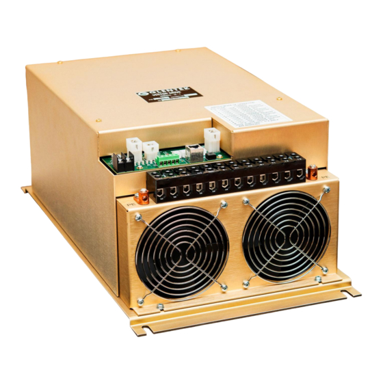
Summary of Contents for Glentek SMB9675-1A-1-7700
- Page 1 INSTALLATION & OPERATION MANUAL Model SMB9675-1A-1-7700 FADAL REPLACEMENT SPINDLE DRIVE MANUAL#: 9675-1035-000 REVISION: (A) DATE: 9 Sep 2015 Fadal is a trademark of Fadal Machining Centers, we have no affiliation with Fadal or Mag IAS...
- Page 2 MANUAL # 9675-1035-000-A...
-
Page 3: Table Of Contents
1.2 I ..................................5 NTENDED PPLICATION 1.3 M ..................................6 ODE OF PERATION CHAPTER TWO: INSTALLING A GLENTEK SPINDLE DRIVE INTO A FADAL VMC ..................7 2.1 R ..................................7 EMOVING THE OLD DRIVE 2.2 M .................................. 7 ECHANICAL NSTALLATION 2.3 E... - Page 4 Table of Contents www.glentek.com APPENDIX C - APPLICATION SOFTWARE ..............................23 C-1 M © ..................................23 OTION AESTRO C-2 I © ................................. 23 NSTALLING OTION AESTRO C-3 C VFD D ........................24 OMMUNICATING ITH THE PINDLE RIVE OR RIVE APPENDIX D - DRAWINGS & DIAGRAMS ..............................25 1 ..............................
-
Page 5: Chapter One: General
Chapter One: General 1.1 Overview The Glentek Inc. SMB9675-1A-1-7700 spindle drive uses flux vector technology to close a torque (current) feedback loop. When applied to a three phase induction motor, the result is servo motor like performance from a standard three phase induction motor. The Digital Signal Processor (DSP) based spindle drive uses its high speed math processing capability to continuously calculate flux and torque vectors and to maintain a constant 90 degree phase difference between the vectors. -
Page 6: Mode Of Operation
Aligning the dial to any of the positions listed below will alter the drive to those settings. If none of the settings below match your preference please contact one of Glentek’s sales engineers for assistance. The drive is shipped with the dial at position 0 (zero) -
Page 7: Chapter Two: Installing A Glentek Spindle Drive Into A Fadal Vmc
Chapter Two Chapter Two: Installing a Glentek Spindle Drive into a Fadal VMC 2.1 Removing the old drive Turn off the power to the VMC and wait 5 minutes before beginning removal. Disconnect all the wires and cables. If any wires are not labeled take note of their location. Of the cables, only the Control cable and the Delta/Wye cable can be confused, both are 6 terminal connectors. - Page 8 Chapter Two www.glentek.com Photo 1: A successful spindle drive installation. Photo 2: Close up of a successful spindle drive installation. MANUAL # 9675-1035-000-A...
-
Page 9: Chapter Three: Initialization And Power Up
VMC. Consult your distributor or Glentek technical support for additional help. The pots can be restored to their starting or “zero” positions by using a voltmeter. - Page 10 Chapter Three www.glentek.com N1 O6000 (RIGID TAP CYCLE) N2 G80 N3 S750 N4 G91 N5 X0.1 Y0.1 G1 F10. N6 M5 N7 G4 P2000 N8 G84.1 Z-1. R+0 F500. Q0.0714 N9 M45 N10 X-0.1 Y-0.1 G1 F10. N11 M45 N12 M45...
-
Page 11: Chapter Four: Troubleshooting And Maintenance
Chapter Four: Troubleshooting and Maintenance 4.1 Status Display Codes Display Name Description Possible Cause Parameter EEPROM Internal problem, EEPROM Fault checksum fault contact Glentek Improper configuration Reset External reset setting Drive processor is in Internal problem, Reset reset contact Glentek... -
Page 12: Chapter Five: Warranty, Factory Repair, And Safety
3. Repackage the unit with the same care and fashion in which it was received. Label the package with the appropriate stickers (e.g. FRAGILE: HANDLE WITH CARE). 4. Contact a Glentek representative, confirm that the unit is being returned to the factory and obtain an RMA (Return Material Authorization) number. The RMA number must accompany the unit upon return to Glentek. -
Page 13: Safety
Chapter Five 5.3 Safety Serious or fatal injury can result from failure to work safely on this equipment. Only qualified personnel should install and maintain this spindle drive. The drive has capacitors that remain charged after the power is shutoff. Wait 5 minutes to allow the capacitors to discharge before removing the cover or working on the drive. -
Page 14: Appendix A - Spindle Drive Connections
Appendix A www.glentek.com Appendix A - Spindle Drive Connections A-1 Motor Power Connectors Table A-1.1 Motor Power Designations Pin # Name Function Input AC LINE 1, three phase AC input Input AC LINE 2, three phase AC input Input AC LINE 3, three phase AC input... -
Page 15: Encoder Input Connector
Appendix A Table A-2.3 Spindle Control Designations: Labeled as P2 on spindle drive Pin # Name Function Spindle Common (for Forward FW /REV COM Input & Reverse) Input REVERSE Spindle Reverse F RW R Input Spindle Forward CMD Common... -
Page 16: Encoder Output Connector
Appendix A www.glentek.com A-4 Encoder Output Connector Table A-4.1 Encoder Output Designations: Labeled as P5 on spindle drive. Pin # Name Function Power Encoder Power Return Output AOut + Encoder Channel A + Output AOut - Encoder Channel A -... -
Page 17: Appendix B - Spindle Drive Connection Interface
Appendix B Appendix B - Spindle Drive Connection Interface This section describes the spindle drive connections and how they are used in the typical application. Refer to the spindle drive’s installation drawing in Drawing & Diagrams. This drawing indicates the location of the pins described below along with the location of the connector they can be found on. -
Page 18: Analog Input, Command Signal
Appendix B www.glentek.com B-3 Analog Input, Command Signal Pins F T/SPEED COM are the command input pins. The command input takes a differential SPINDLE CMD analog signal as referenced to the spindle drive’s ground. Input voltage is expected to range from -10 volts to +10 volts (typical). - Page 19 Appendix B 1.00K +3.3V 10.0K +10V MMBD7000 IRLL014 FROM DSP 1.00K 10.0K TO DSP 40106 HMA124 4.99K 40106 2.00K MMBD7000 TO DSP 1.21K 10.0K 10.0K 0.33uF FAULT HMA124 4.99K AGND 40106 MMBD7000 TO DSP 1.21K 10.0K FORWARD HMA124 4.99K...
-
Page 20: Encoder Feedback
Appendix B www.glentek.com B-5 Encoder Feedback The following pin description defines the main encoder feedback input port. Signal Description ---------- ---------------------------------- Drive supplied 5 volt source (output) A+ / A - Encoder A channel input B + / B -... -
Page 21: Pc Interface
RJ-45 plug and the other end being a DB-9 female connector. Note: If required, Glentek can customize a serial port digital interface to adapt to your controller as required to meet your protocols. We are currently doing this for high speed Ethernet ports. -
Page 22: Power Input And Motor Output
Appendix B www.glentek.com B-9 Power Input and Motor Output The signal names for power are listed below: Pin Name Description -------------- ---------------------------------- L1, L2, L3 Input - AC voltage (line 1, line 2, and line 3, respectively). Protective Earthing, Chassis GND. -
Page 23: Appendix C - Application Software
USB port is also required. It is suggested that you have a minimum of 3 megabytes of application program disk space available prior to installation. C-2.2 MotionMaestro© v1.37 Only MotionMaestro© v1.37 or later will work with Glentek Inc. spindle drives, earlier versions are not compatible. C-2.3 Installation The MotionMaestro©... -
Page 24: Communicating With The Spindle Drive Or Vfd Drive
C-3 Communicating With the Spindle Drive or VFD Drive C-3.1 Serial Port If your PC has a serial port (RS-232), you can connect to the spindle drive with Glentek cable (GTK # GC2400-AL005AM-000). This cable has a female DB-9 (computer) on one end and an RJ-45 (spindle drive) on the other. -
Page 25: Appendix D - Drawings & Diagrams
Drawings & Diagrams MANUAL# 9675-1035-000-A... -
Page 26: Spindle Drive Installation Drawing 2
Drawings & Diagrams www.glentek.com MANUAL # 9675-1035-000-A... -
Page 27: Spindle Drive Connection Diagram
Drawings & Diagrams Vector Drive Connection Diagram Page 1 MANUAL# 9675-1035-000-A... -
Page 28: Spindle Drive Connection Diagram
Drawings & Diagrams www.glentek.com Vector Drive Connection Diagram Page 2 MANUAL # 9675-1035-000-A... -
Page 29: Sensored Vector Command Input Control Diagram
Drawings & Diagrams Sensored Vector Command Input Control Diagram Sensored Vector Command Input Control Diagram Analog Input Analog Input Input Analog Scale Analog to Digital Velocity or Deadband Conversion Current Command (IAD) 32768 MM Set MM Set Input Analog... -
Page 30: Sensored Vector Velocity Control Loop Diagram
Drawings & Diagrams www.glentek.com Sensored Vector Velocity Control Loop Diagram Sensored Vector Velocity Control Loop Diagram Proportional Gain 32768 Gain Velocity Mode 2 Mode 2 Velocity Velocity Loop Error MM Set Velocity Command Error Command Command Integer to Current Loop... -
Page 31: Sensored Vector Current Control Loop Diagram
Drawings & Diagrams Sensored Vector Current Control Loop Diagram Sensored Vector Current Control Loop Diagram Filter 1 Filter 2 Filter 3 Mode 1 Current Command Loop Gain Programmable Programmable Programmable Current Limit (SVC) Set at Unity Gain Biquad Filter... - Page 32 MANUAL # 9675-1035-000-A...
- Page 33 Drawings & Diagrams 208 Standard Street, El Segundo, California 90245, USA. Telephone: (310) 322-3026; Fax: (310) 322-7709 www.glentek.com e-mail: sales@glentek.com MANUAL# 9675-1035-000-A...
Need help?
Do you have a question about the SMB9675-1A-1-7700 and is the answer not in the manual?
Questions and answers