Table of Contents
Advertisement
Quick Links
Advertisement
Table of Contents

Subscribe to Our Youtube Channel
Related Manuals for Doosan GL08K


Summary of Contents for Doosan GL08K
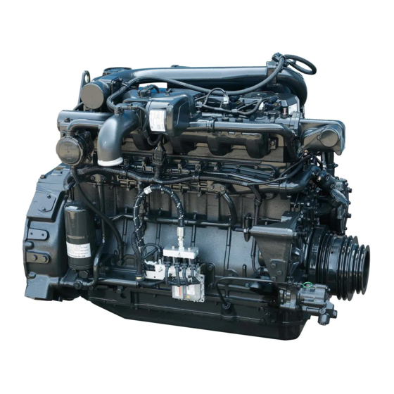
- Page 1 950106-050004EN Operation & Maintenance Manual GAS VEHICLE ENGINE GL08K...
- Page 3 FOREWORD This maintenance manual is designed to serve as a reference for DOOSAN Infracore (here after DOOSAN’s) customers and distributors who wish to gain basic product knowledge on DOOSAN’s GL08K Compressed Nat- ural Gas engine. This economical and high-performance compressed natural gas engine has been so designed and manufac- tured to be used for the overland transport or industrial purpose.
-
Page 5: Table Of Contents
CONTENTS 1. Safety Regulations & Specifications ....................1 1.1. Safety Regulations ..........................1 1.2. Engine Specifications ..........................8 1.3. Engine Power ............................9 1.4. Engine Performance Curve ........................10 1.5. Engine Assembly ..........................12 2. Technical Information ........................16 2.1. Engine Model and Serial Number ......................16 2.2. -
Page 7: Safety Regulations & Specifications
1) Engine starting and operation Before putting the engine into operation for the first time, read the operating instructions carefully and familiarize yourself with the “critical” points. If you are unsure, ask your DOOSAN representative or service man. ... - Page 8 2) Maintenance and care Always carry out maintenance work when the engine is switched off. If the engine has to be maintained while it is running, e.g. changing the elements of change-over filters, remember that there is a risk of scalding. Do not get too close to rotating parts. ...
- Page 9 1) If faults occur, find the cause immediately and have it eliminated in order to prevent more serious of damage. 2) Use only genuine DOOSAN spare parts. DOOSAN will accept no responsibility for damage resulting from the installation of other parts which are supposedly “just as good”.
- Page 10 1.1.5. Notes on safety in handling used engine oil Prolonged or repeated contact between the skin and any kind of engine oil decreases the skin. Drying, irritation or inflammation of the skin may therefore occur. Used engine oil also contains dangerous substances which have caused skin cancer in animal experiments.
- Page 11 4. The use of proper tools and special tools where specified is important to efficient and reliable service operation. 5. Use genuine DOOSAN parts necessarily. 6. Used cotter pins, gaskets, O-rings, oil seals, lock washer and self-lock nuts should be discarded and new ones should be prepared for installation as normal function of the parts can not be maintained if these parts are reused.
- Page 12 1.1.8. Handle compressed natural gas safety Natural gas is highly flammable and explosive and may be extremely cold. The following cautions must be taken to avoid personal injury or engine damage. Do not smoke when installing or servicing the engine or fuel system. ...
- Page 13 1.1.10. Avoid heating near pressurized fluid lines Wear welding goggles and gloves when welding or using an acetylene torch. Insure a that metal shield separated the acetylene and oxygen which must be chained to a cart. Do not weld or heat areas near fuel tanks or fuel lines.
-
Page 14: Engine Specifications
1.2. Engine Specifications GL08K Engine model Items ETPCA/ETPBA BEB00/BEB02 BEB01 Water-cooled, 4 cycle in-line type Engine type Turbo charged & intercooled Ignition system Spark ignition lean burn Combustion chamber type Open dish type Used fuel CNG(Compressed natural gas) Fuel supply system... -
Page 15: Engine Power
GL08K Engine model Items ETPCA/ETPBA BEB00/BEB02 BEB01 Alternator voltage – capacity (V – A) Bus: 24 – 150 Starting motor voltage – output (V – kW) Bus: 24 x 6.0, Truck: 24 x 6.0 Air compressor (cc/rev) Bus: 440, Truck: 300... -
Page 16: Engine Performance Curve
1.4. Engine Performance Curve 1.4.1. Engine performance curve (240PS) 1) Bus (240 PS) 1,200 1,400 1,600 1,800 2,000 2,200 1,000 Revolution (rpm) EJ3OM001 Performance ISO 1585 (SAE J1349) Output (max.) 240ps / 2,300rpm Torque (max.) 90kg m / 1,400rpm • Fuel consumption (min.) 140g / ps... - Page 17 2) Truck (260 PS) 1,400 1,600 1,800 2,000 1,000 1,200 2,200 Revolution (rpm) EJ3OM002 Performance ISO 1585 (SAE J1349) Output (max.) 260ps / 2,300rpm Torque (max.) 100kg m / 1,400rpm • Fuel consumption (min.) 138g / ps • Safety Regulations & Specifications - 11 -...
-
Page 18: Engine Assembly
1.5. Engine Assembly 1.5.1. Engine sectional view (longitudinal) EB8O1003 1. Cooling water pump 13. Ring gear 2. Piston 14. Tappet 3. Air compressor 15. Camshaft 4. Intake valve 16. Oil seal(rear) 5. Exhaust valve 17. Oil seal(rear) 6. Intake valve spring 18. - Page 19 1.5.2. Engine sectional view (cross) ED4OM051 1. Oil filter 7. Spark plug 2. Oil spray nozzle 8. Rocker arm 3. Connecting rod 9. Rocker arm bracket 4. Oil filler cap 10. Exhaust manifold 5. Idle pulley(air compressor) 11. Turbo charger 6.
- Page 20 1.5.3. Engine assembly views 1) Bus engine 14 13 27 28 23 24 EJ3OM003 1. Flywheel housing 11. Oil pan 21. Exhaust manifold 2. Oil pressure sensor 12. Oil drain plug 22. Crank shaft pulley 3. Intake manifold 13. Fuel metering valve 23.
- Page 21 1.5.4. Engine assembly views 1) Truck engine 6 31 32 9 10 15 21 23 25 14 26 12 EJ3OM004 1. Flywheel housing 12. Oil level gauge 23. Crhank shaft pulley 2. Engine rpm sensor 13. Oil pan 24. Vibration damper 3.
-
Page 22: Technical Information
They are also referred to as engine model and serial number because of their location. EJ3OM005 Engine serial No. (example 1 : GL08K Bus) GL08K 1 00001 BA Engine model suffix (ETPBA) Serial no. Production year (2011) Engine model ... -
Page 23: Diagnostic Tool (Scan-200)
Deutsch HD16-9-1939S Deutsch EI4OM007 2.3. Engine Character The GL08K compressed natural gas engine is an overhead valve, turbo charged, air-to-air charge cooled, electronically controlled engine. Spark-ignited, lean burn combustion Electric engine control through the ECM(engine control module) system ... - Page 24 2.3.3. Engine timing Camshaft, oil pump and ignition timing sensor gear are driven by a gear train arranged at the front end. Ignition timing sensor gear Camshaft gear (Z=54) (Z=54) Idle gear (Z=42) Crank shaft gear (Z=27) Oil pump idle gear (Z=23) Oil pump drive gear (Z=36)
- Page 25 2.3.5. Lubrication system The engine is equipped with force-feed lubrication. The pressure is produced by a gear pump whose drive gear is in direct mesh with the crankshaft gear at the front end of cylinder block. The oil pump draws the oil from the oil sump and delivers it through the oil cooler and oil filter to the main distributor gallery and from there to the main bearings, big-end bearings and camshaft bearings as well as to the small-end bearings and the rocker arms.
- Page 26 (city bus, truck) The following oils are also recommended SAE No. Sulfated ash content 15W40 Bellow 0.5 % * Use only Doosan Infracore recommended engine oil. Engine Oil capacity Engine oil capacity Oil pan inside Engine Total Vehicle...
- Page 27 2.3.7. Oil cooler An oil cooler is provided between the oil filter and the cylinder block. Oil cooler This cooler is a flat tube type with turbulence inserts and operated by the coolant. Cooling water outlet Cooling water inlet ED4OM008 2.3.8.
- Page 28 2.3.10. Fuel system The fuel system consists of the fuel(CNG) tank, fuel regulator, fuel metering valve, air-fuel mixer and fuel lines such as pipes and hoses. All parts are should be carefully managed because the fuel pressure in this system is very high. Leak check should be performed regularly to all connections. ...
- Page 29 2.3.11. Spark plug Remove spark plug. Clean threads by hand with brush and solvent. Clean any deposits from electrode and Inspect insulator area Measure the spark plug distance at electrode position.(A) Replace spark plug if necessary. Standard Distance (A) 0.39 ~ 0.40 mm...
- Page 30 2.3.12. Engine control module : ECM This engine control module is used to Engine control module J1-C control the engine for a natural as (ECM) J1-B application. It is used in conjunction J1-A with various actuators, sensors, etc to make up a system.
- Page 31 2.3.14. Ignition control system The ignition control system uses a direct-fire, one coil per cylinder, coil on plug inductive ignition system. The non adjustable spark timing is controlled by the ECM based on engine speed, ECT and MAP sensor. Ignition coils Spark plugs Main harness...
- Page 32 2.3.16. Turbocharger The exhaust gases of the engine are passed through the turbine rotor of the turbocharger. Air compressor impeller mounted on the same shaft draws in fresh air and delivers it at a higher pressure to the cylinders. ...
- Page 33 2.3.18. Cooling system The engine has a liquid-cooling system. The fresh water pump is a maintenance-free by gear from the crankshaft. Depending on the agreed extent of delivery and the design of the engine, the coolant circuit can be equipped with temperature monitors which, in the event of loss of coolant ...
- Page 34 (example : if the color of NITRITE pad is between standard color “D” and “F”, then use column E) Since GL08K cylinder liner is dry type, particularly the cooling water control should be applied thoroughly. The density of antifreezing solution and additive for rust prevention is able to be confirmed by the cooling water test kit.
- Page 35 NOTE : However, it should not elapse longer than 75 sec, and if it did, the hue would change. (4) Make the numerical value by comparing the test paper which hue has changed with the color list of label on storage bottle. (5) By comparing the hue changed into yellowish green or so with the green color indication of test paper storage bottle, confirm the density.
- Page 36 As for the valve clearance, adjust it when in cold, as follow. Model Intake valve Exhaust valve GL08K 0.3 mm 0.3 mm – By cranking the engine, let #6 cylinder's valves overlap. – In time, adjust the valve clearance corresponding to "...
- Page 37 2.3.23. Cylinder compression pressure Stop the engine after warming up, and Ignition coil take out spark plug. Cover (Ignition coil) EJ3OM027 Install the special tool (compression gauge adapter) at the spark plug hole Gauge adapter Compression pressure gauge and connect the compression pressure gauge there.
- Page 38 2.3.25. Starting motor The sliding-gear starter motor is flanged to the rear of the flywheel housing on the left-hand side. As parts of every engine overhaul, the starter pinion and ring gear should be cleaned with a brush dipped in fuel and then a coat of grease should be applied again.
- Page 39 Vietnam Specifications 24V x 6.0kW Battery terminal Terminal switch M10 x P1.5 M5 x P0.8 EGL0818007 Wiring harness EGL0818008 Technical Information - 33 -...
- Page 40 2.3.26. Alternator 1) Alternator (28.5V x 80A) The alternator is fitted with integral silicon rectifiers. A transistorized regulator mounted on the alternator body interior limits the alternator voltage. The alternator should not be operated except with the regulator and battery connected in circuit to avoid damage to the rectifier and regulator. 28.5V x 80A Battery ground M6 X 1.0...
- Page 41 Vietnam Specifications 2) Alternator (28.5V x 150A) The alternator is fitted with integral silicon rectifiers. A transistorized regulator mounted on the alternator body interior limits the alternator voltage. The alternator should not be operated except with the regulator and battery connected in circuit to avoid damage to the rectifier and regulator. 24V x 150A E - Terminal Battery Terminal...
-
Page 42: Diagnosis And Remedy
2.4. Diagnosis and Remedy The following description summarizes the probable cause of and remedy for generall failure by item. Inspect the electrical parts problem with SCAN-200 and refer diagnostic manual. Immediate countermeasures should be taken before a failure is inflamed if any symptom is detected. 1. - Page 43 2. Engine overheated Operating state 1. Overload Cooling system 2. Radiator core clogged 3. Continuous over-run Check coolant level Normal Too low Check fan belt tension, wear or damage etc. Normal Inspect cooling water leakage Normal Repair External Internal Replace Retighten Engine Check fresh radiator tank cap...
- Page 44 3. Output insufficient Inspect by SCAN-200 Engine Chassis diagnostic tool Check for clutch slip Inspect gas fuel filter Adjust or replace clutch Others Polluted Inspect air cleaner Repair Normal Repair Normal Replace Replace Inspect air leakage Inspect ignition timing of air piping line Check valve clearance Normal Adjust...
- Page 45 4. Oil pressure lowered Check if oil pressure gauge indicates wrongly Check oil amount Normal To low Check cooling temperature Use recommened oil (replenish) Normal Too high Inspect oil quality Refer to engine overheat Normal Check oil relief valve Water mixed in oil Improper Retighten Disassemble engine...
- Page 46 5. Fuel consumption excessive Case according to use conditions 1. Overload 2. Frequence use of low gear position at high speed 3. Frequence use of high gear position Inspect nature gas leakage at low speed 4. Clutch slip 5. Too low tire inflation pressure Normal Nature gas leakage Retighten...
- Page 47 6. Oil consumption excessive Case according to use conditions 1. Excessive oil infusing 2. Continuous operation in low speed or extremely cold state Inspect oil leakage Inspect air cleaner Clean . Replace Normal Oil leakage Check oil quality External Internal Replace with specified oil Retighten Check compressed pressure...
- Page 48 8. Battery discharge Battery Wiring, Switch Alternator Check electrolytic liquid amount Inspect cut wire shorts and Check fan belt tension & damage loose connections Normal Abvormal Repair . Replace Adjust Check charged stated Replace Discharging Disassemble alternator Voltage regulator Normal Battery room damage Battery self dischage Battery over charging...
- Page 49 Condition Causes Remedies 1) Starting difficult (1) Compression pressure Valve's poor shut, stem distortion Repair or replace Valve spring damage Replace valve spring Cylinder head gasket's leak Replace gasket Wear of piston, piston ring or liner Adjust 2) Idle operation abnormal ...
- Page 50 Condition Causes Remedies (3) Piston, piston pin & Piston clearance increase as the wear of Replace piston & piston and piston ring progresses piston ring piston ring Wear of piston or piston pin Replace Piston stuck Replace piston ...
-
Page 51: Engine Inspection
2.5. Engine Inspection 2.5.1. Stopping engine Checking the engine for any unusual condition at the idling speed, then turn the key switch to stop the engine. 2.5.2. General engine inspection cycle : Check & adjust : Replace Inspection time (km) Inspection Daily Remark... -
Page 52: Maintenance
3. Maintenance 3.1. Engine Disassembly 3.1.1. Heed at disassembly Before disassembly, the part shelf should be prepared for various tools and repair parts. When assembling, clean empty hand should be used and clean environment maintained. In case of storing the disassembled parts, each part should not touch each other. ... - Page 53 3.1.4. Engine oil Remove the oil drain plug of oil pan and pour the engine oil into the prepared vessel. Drain plug ED4OM015 3.1.5. Engine control module : ECM Disconnect the engine control Engine control module J1-C module(ECM) and wiring harness. (ECM) J1-B ...
- Page 54 3.1.8. Alternator (Applies to some models only) Remove the alternator fixing bolts and take off the alternator. 3.1.9. Guide tube Unscrew flange nut on th oil pan and remove the guide tube. EQM3005I 3.1.10. Breather Unscrew the hose clamp and remove the breather hose.
- Page 55 3.1.12. Intercooler Tear down the various hoses and air Air outlet pipes from the inter cooler. Air flow Remove the intercooler fixing bolts and Air inlet tear it down. EG9OM040 3.1.13. Throttle valve Unscrew throttle valve fixing bolts and remove the throttle valve with gasket on Throttle Valve the intake manifold...
- Page 56 3.1.15. Turbo charger Remove the oil supply pipe and oil return pipe between the turbo charger and the cylinder block. Unclamp the rubber hose connected the intercooler and air cleaner. Unscrew the turbo charger fixing nuts and take off the turbo charger from the exahust manifold.
- Page 57 3.1.19. Water pump Unclamp the rubber hose connected to the oil cooler. Unscrew the water pump fixing bolts from the cylinder block and take off the water pump. EB5M3011 3.1.20. Starter Unscrew the starter fixing nuts and remove the starter being careful not to damage its gears.
- Page 58 3.1.23. Oil filter Remove the oil filter fixing bolts and take off the oil filter. EB8M3002 3.1.24. Power steering pump Remove the oil hose between power steering oil pump and control unit of the vehicle. Unscrew the power steering oil pump fixing bolts and remove the power steering pump.
- Page 59 3.1.27. Timing gear case cover Disassemble the oil seal using an oil seal removing jig. Remove the cover fixing bolts and disassemble the cover from the timing gear case. EAMD025I 3.1.28. Cam shaft gear and idle gear Unscrew the camshaft gear fixing bolts and remove the camshaft gear.
- Page 60 3.1.31. Rocker arm Remove the rocker arm bracket fixing bolts in reverse order (zigzag method) of assembling and disassemble the rocker arm. Take out the push rod upwards. Disassembly of rocker arm assembly - Remove the snap ring from the both ends of rocker arm shaft by means of a plier.
- Page 61 3.1.33. Cylinder head Remove the cylinder head bolts in the reverse order of tightening but remove it step by step. First step : Loosen 1 ~ 2 threads Second step : Remove by loosening fully. However, remove the total bolts simultaneously by the step of 1 and 2.
- Page 62 3.1.34. Oil cooler Loosen the cooling water pump and the rubber hose clamps of connected pipes, and disassemble it. Remove the oil cooler fixing bolts and take off the oil cooler. EB5M3008 3.1.35. Oil pan Unscrew the oil pan fixing bolts and remove the oil pan.
- Page 63 3.1.37. Piston and connecting rod Remove the connecting rod cap bolts in the reverse order of assembling but do same as the cylinder head bolt removal. Disassemble the upper/lower of connecting rod caps by tapping lightly with urethane hammer, and remove the bearing.
- Page 64 3.1.38. Cylinder liner Disassemble the cylinder liner with a special tool or hand but be careful not to generate any damage at cylinder block. EAMD040I 3.1.39. Cooling water chamber cover Unscrew the fixing bolts and remove the water chamber cover. ...
- Page 65 3.1.42. Fly wheel housing Remove the flywheel housing fixing bolts and disassemble the flywheel housing. Oil seal ED4OM017 3.1.43. Camshaft and tappet In order for camshaft not to be damaged, disassemble turning it. In order for the disassembled camshaft to be prevented from bends or damage, put it on the special lathe and store.
- Page 66 3.1.46. Bearing cap Remove the bearing cap assembling bolts by the step in the reverse order of assembling, and disassemble the bearing cap. (Remove by the same way as the cylinder head bolts' removal.) Disassembled bearing caps are kept laid in order.
-
Page 67: Inspection And Measurement On Major Parts
3.2. Inspection and Measurement on Major Parts 3.2.1. Cylinder block Clean the cylinder block thoroughly, and check for any crack or damage. If there is any crack or severe damage, replace it and if there is minor one, correct it. ... - Page 68 2) Distortion at the lower face a) Check for the cylinder head. Remove carbon from the cylinder head lower surface, and then should be careful not to scratch the surface. Check any crack or damage that can not found by naked eyes through the hydraulic or magnetic particle test.
- Page 69 3.2.3. Spark plug Remove spark plug. Clean threads by hand with brush and solvent. Clean any deposits from electrode and inspect insulator area Measure the spark plug distance at electrode position (A). Correct or replace the spark plug if necessary.
- Page 70 Valve head thickness Measure the thickness of valve head and if beyond the limit value, replace the valve. Dimension Standard Limit Description 2.2 mm or Intake valve 2.7 mm more 1.7 mm or Exhaust valve 2.2 mm EFM2037I more 2) Valve guide ...
- Page 71 Valve Valve seat EA0M4046 For the disassembling of valve seat, by welding the welding bead to a Valve seat valve seat rotating tool or valve seat, insert pull it out with a special tool. For the assembling of a new valve Cylinder head seat, by putting it among the dry ices of an ice box previously for about 2...
- Page 72 Valve spring inclination Use a surface plate and a square to measure the valve spring inclination. Inclination If the measured value exceeds the specified limit, the valve spring must be replaced. (unit : mm) Standard Limit Valve spring Less than 2.7 mm Square inclination...
- Page 73 3.2.5. Rocker arm assembly 1) Disassembly Disassemble the snap rings that are located at both ends of rocker arm shaft by a plier. Disassemble in the order of washer, rocker arm bracket, rocker arm spring, rocker arm. EA8M3008 2) Inspection of rocker arm assembly a) Rocker arm shaft ...
- Page 74 Rocker arm bushing diameter Measure the inside diameter of the rocker arm bushing with an inside micrometer or vernier calipers, compare measured values with the rocker arm shaft diameter. If the clearance exceeds the limit, replace either bushing or shaft, whichever worn more.
- Page 75 Push rod run-out Use a feeler gauge to measure the push rod run-out. Roll the push rod along a smooth flat surface as shown in the figure Limit 0.3 mm or less d) Reassembling rocker arm assembly Feeler gauge Reassembling can be done in the EA0M4073 reverse order of disassembling and...
- Page 76 Cam surface Inspect the cam face for scratch or damage. Slight step wear or damage on the cam face may be corrected with oil stone or oiled grinding paper. But, replace if severely damaged. 3) Cam shaft Clearance between camshaft journal and camshaft bush With an outside micrometer, measure the camshaft journal diameter.
- Page 77 b) Wear measuring With an outside micrometer measure the diameter of the crankshaft journals and pins in the directions as shown, and compare the measured values to determine the amount of wear. EAMD057I If the amount of wear is beyond the limit, have the crankshaft ground and install undersize bearings.
- Page 78 * "R" parts specified value (1) Crank pin's "R" : 4.5 -0.2 (2) Crank Journal "R" : 4 -0.2 CAUTION : In case of regrinding, the grinding the "R" part of bearing end should be correctly done and keep in mind to remove any jaws or coarse surface absolutely. c) Crankshaft run-out ...
- Page 79 c) Connecting rod bearing clearance Install the connecting rod bearing in the connecting rod bearing cap, tighten the connecting rod cap bolts to the specified torque, then measure the inside diameter. 1st Step 4 kg • Torque 2nd Step 60°...
- Page 80 Spread = O A - O B EDM2047I Crankshaft bearing crush Install the bearing and cap in the cylinder block, retighten the bolts to specified torque, unscrew out one bolt completely, then measure the clearance between the bearing cap and cylinder block using a feeler gauge.
- Page 81 3.2.8. Piston assembly 1) Disassemby of piston assembly Disassemble piston according to the disassembly process 2) Piston inspection a) Visual check Visually check the pistons for cracks, scuff or wear, paying particular attention to the ring groove. b) Clearance between the piston and cylinder liner ...
- Page 82 3) Piston inspection a) Visual check Replace the piston rings with new ones if detected worn or broken when the engine is overhauled. b) Piston ring gap Insert the piston ring into the upper portion of the cylinder liner bore so that it is held at a right figure to the cylinder liner wall.
- Page 83 4) Piston pin inspection a) Wear Measure the amount of wear on the piston pin at the points as shown. The measured values are beyond the limit (0.08 mm or greater), replace the pin. Standard Limit 41.994 ~ 42.000 mm 41.94 mm EA0M4031 b) Clearance...
- Page 84 5) Connecting rod inspection a) Distorsion Check the connecting rod for distortion. As shown in the figure below, install the connecting rod to the connecting rod tester, and check for distortion using a feeler gauge. If the connecting rod is found distorted, never re-use it but replace with a new one.
-
Page 85: Engine Reassembly
3.3. Engine Reassembly 3.3.1. General precautions Clean all the disassembled parts, particularly oil and water ports, using compressed air, then check that they are free from restrictions. Arrange the general and special tools in order for engine assembly operation. ... - Page 86 3.3.5. Tappet and cam shaft Undercool a new bush with dry ice for about 2 hours and press it into position in the cylinder block using a bench press. After the pressing operation, measure the inside diameter of the cam bush to check if it is not deformed.
- Page 87 Heat the crankshaft gear for at least 10 minutes to 120°C, then apply sealant (Loctite # 641) to the inside wall of the heated crankshaft gear evenly before inserting it to the end of crankshaft. EA8M3014 Semi-tighten a bolt at both sides of the crankshaft, apply engine oil to journals and pins, then assemble the crankshaft with the cylinder block by tightening the...
- Page 88 Install the bearing cap by matching the cylinder block No. with the bearing cap No. EAMD078I Apply oil to the entire part of the bearing cap bolts, then tighten in tightening sequence to specified torque. Torque 30 kg •...
- Page 89 When the bolts are tightened, remove the guide bar. The flywheel housing is assembled after the new oil seal was pressed (Coat engine oil over the outside of oil seal) before in the housing by a press. If any peripheral scar was generated due to oil seal at the oil seal contact surface of crankshaft, after inserting about 1mm shim or thereabout in front of oil seal (Direction toward crankshaft.), measure and adjust.
- Page 90 Install a guide bar into a bolt hole on the crank shaft, and lift the flywheel to align the dowel pin with the pin hole on the flywheel for temporary assembly operation. Coat the adhesive (#271 Loctite) over the assembling bolts and install bolts in the remaining holes.
- Page 91 3.3.11. Cooling water chamber cover Coat the adhesive over the water chamber cover (Particular around bolt holes) and after attaching the gasket, assemble it to the cylinder block using the bolts for assembling. As for tightening of bolts, after primarily tightening the bolts located at the both ends of cover (4ea at both sides) and middle bolts (Upper, lower 2ea) , tighten the rest.
- Page 92 Install the idle gear by coinciding the marks impressed on the crank gear, Mark "2" cam gear, ignition taming drive gear, Camshaft gear Ignition timing and idle gear. drive gear Install a thrust washer on the idle gear Idle gear and tighten to specified torque.
- Page 93 3.3.16. Piston and connecting rod Use a piston heater to heat the piston approximately 100 °C (212 °F) for 5 minutes. EA3M2058 Align the piston pin hole with the oiled connecting rod small end and press the piston pin (by lightly tapping with a rubber hammer) to assemble the connecting rod with the piston.
- Page 94 Marked with the name of piston ring manufacturing company ED4OM023 Adjust the angle among individual Top Ring Gap piston ring gaps to 120° and fit a piston assembling jig onto the piston, Use care not to match the ring gaps with the pin direction.
- Page 95 Wet the fixing bolts with engine oil, semitighten them with hand, tighten them to the specified torque using a torque wrench as follows. 60° EGL0818006 <Tightening order> (1) Second stage : Temporary bolt screwing about 1 ~ 2 threads (2) Second stage : Tighten the bolt using a torque wrench to a torque of 4 kgf·m.
- Page 96 3.3.18. Cooling water pump Mount a new gasket. Install the water pump on the cylinder block and tighten the assembling bolts with specified torque. Torque 2.2 kg • Connect water pipes and by-pass pipe to the water pump. ...
- Page 97 3.3.21. Vibration damper Insert the vibration damper to the crankshaft, and assemble by tightening the assembling bolts at the specified tightening torque according to bolt tightening order. (refer to right figure.) Torque 13.4 kg • EAMD111S EDM2089I 3.3.22. Oil pan ...
- Page 98 Align the bolt holes with gasket holes to prevent damage to the gasket and tighten. 3.3.23. Oil filter Install the oil filter onto the cylinder block, and tighten the fixing bolts. Torque 2.2 kg • Apply engine oil to the oil filter cartridge oring and assemble the cartridge using a filter wrench.
- Page 99 3.3.26. Intake and exhaust valves Identify the marks of "IN" and "EX" impressed on the valve head before assembling the valve with the valve head. With a valve stem seal fitting jig, assemble the valve stem seal on the valve guide.
- Page 100 Check the inside of combustion chamber for foreign substances, and carefully mount the cylinder head assembly in the block by aligning the dowel pin with the dowel pin hole. Be careful not to damage the cylinder head gasket. If the dowel pin is not in alignment, lift the cylinder head again and then remount it.
- Page 101 3.3.28. Rocker arm assembly Apply lubricating oil to the rocker arm bush and shaft, and assemble the intermediate bracket with the rocker arm (rocker arm assembly) on the cylinder block using fixing bolts. In tightening the bolts, it must be done at the specified value using zigzag method.
- Page 102 3.3.31. Exhaust manifold Install the exhaust manifold gasket over the stud bolts by aligning the gasket with the exhaust port on the cylinder head so that the face and back of the gasket can be positioned correctly. Semi-assemble the exhaust manifold and install the heat resisting plate.
- Page 103 3.3.33. Ignition coil and spark plug Apply the sealant (Locktite #272) the ignition coil cover into the cylinder head, then tighten. Tighten the spark plug at cylinder head Ignition coil with socket tool. Assemble the ignition coil onto ignition coil cover.
- Page 104 Model Intake valve Exhaust valve GL08K 0.3 mm 0.3 mm CAUTION: Crankshaft revolution is done by hands without using a starting motor. Turn it to the direction of engine rotation, but do not use the installing bolts at the turn.
- Page 105 3.3.35. Ignition control module (ICM) Assemble the ignition control module Ignition control module (ICM) by using the fixing bolts. (ICM) Ignition coil harness EJ2OM003 3.3.36. Fuel metering valve Assemble the metering valve by using the fixing bolts. Install the metering valve on the fuel delivery and suction hose.
- Page 106 3.3.39 Air compressor & power steering pump Couple the power steering oil pump to the air compressor with the driving dog engaged. Insert the O-ring coated with grease into the oil outlet of the air compressor. Place the air compressor on the mounting bracket carefully and tighten the fixing bolts to the specified torque.(Carefully damage the O-ring)
- Page 107 3.3.43. Cooling fan Install the flange to the water pump pulley, then assemble the cooling fan to the pulley by tightening the fixing bolts. Torque 2.2 kg • EA9M3001 3.3.44. Cooling fan guide Assemble 3 cooling fan brackets and fan guide bracket.
- Page 108 ( ) on the flywheel housing. Model GL08K Timing check hole Ignition timing 10° (B.T.D.C static) Ignition timing mark...
- Page 109 Placed in the ignition timing mark on the crankshaft pulley. Timing pointer ED4OM059 3.3.47. ECM, ICM and harness Assemble the engine control Engine control module J1-C module(ECM) and Ignition control (ECM) J1-B module(ICM) on the cylinder block. J1-A ...
-
Page 110: Major Electric Parts Replacement
3.4. Major Electric Parts Replacement CAUTION: Do not connect or disconnect the ECM to/from the wiring harness without first removing the negative(-) battery cable from the battery. 3.4.1. Engine control module(ECM) replacement <Removal> Engine control module J1-C 1) Close the manual shut off valve. (ECM) J1-B 2) Disconnect the battery ground cable. - Page 111 3.4.3. Fuel filter replacement <Removal> 1) Close all fuel cylinder manual valves. On cylinders with electronic in tank valves, disconnect the electrical harness connectors from the tank valves. CAUTION: Always close the fuel cylinder valves before servicing the system. Close the valves using the valve manufactures recommended procedure.
- Page 112 3.4.4. High pressure lock-off valve replacement <Removal> 1) Close all fuel cylinder manual valves. On cylinders with electronic in tank valves, disconnect the electrical harness connectors from the tank valves. CAUTION: Always close the fuel cylinder valves before servicing the system. Close the valves using the valve manufactures recommended procedure.
- Page 113 <Installation> 1) Inspect the O-rings on the fittings for nicks, cuts, or damage that may affect their sealing ability. Replace the O-rings as necessary with the proper size and type. 2) Lubricate the O-rings with white lithium grease or a commercial O-ring lubricant. 3) Install the inlet and outlet fittings on the high-pressure lock-off valve.
- Page 114 3.4.5. Ignition control module (ICM) replacement <Removal> 1) Close the manual shut off (1/4 turn) Ignition control module valve. (ICM) 2) Disconnect the battery ground cable. 3) Disconnect the 3 harness connectors from the ICM. 4) Remove the ICM mounting hardware. <Installation>...
- Page 115 10) Remove the fuel-metering valve. CAUTION: The fuel-metering valve may be serviced as an assembly or repaired with replacement parts from Woodward or DOOSAN Infracore Company. <Removal> 1) Install the metering valve. 2) Connect the mixer fuel hose to the fuel metering valve outlet and inlet.
- Page 116 3.4.7. Natural gas pressure (NGP) sensor <Removal> 1) Close all fuel cylinder manual valves. On cylinders with electronic in tank valves, disconnect the electrical harness connectors from the tank valves. CAUTION: Always close the fuel cylinder valves before servicing the system. Close the valves using the valve manufactures recommended procedure.
- Page 117 CAUTION: Always close the fuel cylinder valves before servicing the system. Close the valves using the valve manufactures recommended procedure. Check for multiple cylinders and close all the valves before proceeding. Do not close the manual shut off (1/4 turn) valve. 1) Relieve fuel pressure by running the engine until it stops.
- Page 118 CAUTION: Always close the fuel cylinder valves before servicing the system. Close the valves using the valve manufactures recommended procedure. Check for multiple cylinders and close all the valves before proceeding. Do not close the manual shut off (1/4 turn) valve. 2) Relieve fuel pressure by running the engine until it stops.
- Page 119 3.4.10. Regulator replacement <Removal> 1) Close all fuel cylinder manual valves. On cylinders with electronic in tank valves, Natural gas outlet disconnect the electrical harness connectors from the tank valves. Cooling water inlet CAUTION: Cooling water outlet Always close the fuel cylinder valves Natural gas inlet before servicing the system.
- Page 120 CAUTION: Before serving any fuel system component make certain that the fuel cylinder valves are fully closed and the fuel line pressure properly relieved. Failure to do so could result in serious personal injury and/or damage to property. 9) Slowly disconnect the high-pressure fuel line from the regulator. 10) Remove the NGTP sensor from the regulator.
- Page 121 3.4.11. Wastegate control valve replacement <Removal> 1) Close the manual shut off (1/4 turn) valve. Air pressure 2) Disconnect the battery ground cable. from regulator 3) Disconnect the harness connector from Compressed air the wastegate control valve. from turbocharger 4) Disconnect the two hoses connected to Solenoid the wastegate control valve.
-
Page 122: Electrical System
3.5. Electrical System 3.5.1. Electrical component of engine 1) Bus engine EJ3OM022 1. Oil pressure sensor 7. Turbocharger solenoid valve 2. Throttle valve 8. Cooling water temperaature sensor 3. Pre throttle pressure sensor (PTP) 9. Ignition coil 4. Gas Pressure and temperature sensor 10. - Page 123 2) Truck engine EJ3OM023 1. Oil pressure sensor 7. Turbocharger solenoid valve 2. Throttle valve 8. Cooling water temperaature sensor 3. Pre throttle pressure sensor (PthP) 9. Ignition coil 4. Gas Pressure and temperature sensor 10. Humidity sensor 5. Fuel metering valve 11.
- Page 124 3.5.2. Engine control system ED2OM049 - 118 - Maintenance...
- Page 125 3.5.3. Engine control harness 1) Main harness UEGO Ignition Water Switch 6110-4623 (Sans Ho) TYCO_1897013-2 Oil Sensor AMP_85202 AMP_2450153 MG368162-1ALT MG610320 EDM-HD Engine ground Deutch_DT06-12SB TYCO_1897013-2 NGTP PED_12065287 Interconnector #7 HDP24-24-33PN MG640348 Interconnector #6 4-1437287-7(32P) 4-1437287-5(24P) J2-A J2-B J1-C J1-A 4-1437287-5(24P) 4-1437287-6(24P)
- Page 126 Truck Throttle Eengine Control Module (ECM) 4-1437287-5(24P) UEGO Ignition J1-C 4-1437287-6(24P) MAPT 4-1437287-6(24P) J2-B 4-1437287-5(24P) J1-B Engine Ground J1-A J2-A Waste Gate Solenoid 4-1437287-7(32P) NGTP EDM-HD Interconnector #7 IC#6 IC#3 IC#4 Interconnector #5 EJ1OM026 Connector Connector Part Name Part Name (Harness) (Harness) J1-A...
- Page 127 Injector EJ1OM028 Connector Connector Part Name Part Name (Harness) (Harness) P5 ~ P12 Injector Natural gas temperature sensor (NGT) Natural gas pressure sensor (NGP) Fuel metering valve Maintenance - 121 -...
- Page 128 2) Main harness Throttle MAPT 1 928 403 736 AMP_368162-1ALT Ignition Humidity Ground CYL #6 Waste gate solenoid CYL #5 CYL #4 CYL #3 CYL #2 CYL #1 Water Sensor Humidity EJ1OM029 Connector Connector Part Name Part Name (Harness) (Harness) Pre throttle pressure sensor (PTP) P41 ~ P46...
- Page 129 Truck Ignition 1 928 403 736 AMP_368162-1ALT Humidity CYL #5 CYL #4 CYL #6 CYL #2 CYL #1 CYL #3 Humidity EJ1OM031 Connector Connector Part Name Part Name (Harness) (Harness) Ignition Humidity sensor P41 ~ P46 Ignition coil Maintenance - 123 -...
- Page 130 3.5.4. Kits and electric parts 1) Air pressure regulator This self-operated, small-volume air pressure regulator provides constant Air regulator reduced pressure to pneumatic controller. Downstream air pressure increase above the outlet pressure setting moves the diaphragm assembly, venting the excess pressure through a hole drilled or tapped in the spring EB3O606I case.
- Page 131 3) Heat exchanger The expansion of pressurized gas Cooling water outlet from fuel tank as it passes through the pressure regulator causes Cooling water inlet extremely low fuel temperatures. Fuel metering component materials Gas inlet downstream of the regulator are only rated for -40°C (-40°F).
- Page 132 5) Fuel metering valve After the compressed natural gas Gas outlet from a gas tank passes through the pressure regulator to the pressure level of 8bar, it is warmed in the heat exchanger. The fuel gas flows Gas temperature sensor through the gas thermostat element and the Fuel Metering Valve.
- Page 133 8) Manifold absolute pressure sensor : MAP The manifold boost pressure(MAP, PthP) sensor detects the absolute air and fuel pressure within the engine manifold. Information from this sensor, along with air charge temperature information is used to calculate density of the mass charge being delivered to each cylinder.
- Page 134 11) Spark plug Spark plugs play a critical role in the proper operation of this engine. The natural gas conversion uses a special spark plug designed specifically for this type operation. Features of this plug include a smaller spark plug gap than the typical gasoline applications.
- Page 135 13) Wastegate control solenoid Turbocharger boost control is Air pressure achieved by using a turbo with a from regulator conventional diaphragm wastegate Compressed air actuator and a pulse width modulated from turbocharger (PWM) wastegate control solenoid. Solenoid When the solenoid is operated the valve wastegate closed and opening.
- Page 136 16) Other sensor (1) Engine cooling water temperature : ECT The Engine Coolant Temperature sensor is a thermistor (temperature sensitive resistor) located in the engine cooling water pipe. It is used in the engine airflow calculation, and to enable certain features. ...
- Page 137 3.5.5. Engine control module (ECM) 1) Engine control input/output Terminal Terminal Connector Terminal No. Wire Description Signal Name Symbol Pin no. AEXF 0.85 L/Y ECU J1-C15 AN27_ECT FLR91X-A 0.75 L/R ECU J1-B21 LSU1_UN FLR91X-A 0.75 L/R ECU J1-B15 LSU1_IA FLR91X-A 0.75 L/R ECU J1-B20 LSO1_LSUH2...
- Page 138 Terminal Connector Terminal No. Wire Description Signal Name Symbol Pin no. AEXF 0.85 W ECU J2-A1 INJ1 AEXF 0.85 W ECU J2-A3 INJ2 AEXF 0.85 W ECU J2-A7 INJ3 AEXF 0.85 W ECU J2-A6 INJ4 AEXF 0.85 W ECU J2-A8 INJ5 AEXF 0.85 W ECU J2-A5...
- Page 139 Terminal Connector Terminal No. Wire Description Signal Name Symbol Pin no. AEXF 0.85 L P40 CONN 9 AEXF 0.85 R P40 CONN 10 AEXF 0.85 L P40 CONN 12 AEXF 0.85 L/Y P40 CONN 14 AEXF 0.85 V P40 CONN 18 AEXF 0.85 V P40 CONN 19 AEXF 0.85 L/B...
- Page 140 Truck Terminal Connector Terminal No. Wire Description Signal Name Symbol Pin no. AEXF 0.85 L/Y ECU J1-C15 AN27_ECT AEXF 0.85 L/R ECU J1-B21 LSU1_UN AEXF 0.85 L/R ECU J1-B15 LSU1_IA AEXF 0.85 L/R ECU J1-B20 LSO1_LSUH2 AEXF 0.85 L/R ECU J1-B1 LSU1_VM AEXF 0.85 L/R...
- Page 141 Terminal Connector Terminal No. Wire Description Signal Name Symbol Pin no. AEXF 0.85 R ECU J2-A18 AEXF 0.85 R ECU J2-A19 AEXF 0.85 R ECU J1-B11 SPLICE AEXF 0.85 R ECU J1-A11 AEXF 0.85 B ECU J1-B24 AEXF 0.85 B ECU J1-A24 AN21_ELEVATED IDLE/ AEXF 0.85 G...
- Page 142 Terminal Connector Terminal No. Wire Description Signal Name Symbol Pin no. AEXF 0.85 Br P40 CONN 3 AEXF 0.85 Br P40 CONN 6 AEXF 0.85 Br P40 CONN 2 AEXF 0.85 Br P40 CONN 4 SPLICE AEXF 0.25 R P40 CONN 21 AEXF 0.85 R P40 CONN 10 AEXF 0.85 L/B...
- Page 143 2) ECM power description Harness Signal Connector Wire Connector Function Name Pin No. color Pin No. P16-A, P50-A, ECT, NGTP, Interconnector #7, XDRG_A J1-B24 Black P61-28, P40-8 Ignition P61-9, P63-10, Interconnector #7, FMV, XDRG_B J1-A24 Black P40-15 Ignition J2-A18 DRVP P25-F, P63-9 Interconnector #6, FMV...
- Page 144 3) Ignition signal connection description Harness Signal Connector Wire Connector Function Name Pin No. color Pin No. P40-3 P62-2 Brown EDM-HD Ignition coil #3 (Cylinder #3) P40-5 P62-3 Brown EDM-HD Ignition coil #5 (Cylinder #2) P40-1 P62-1 Brown EDM-HD Ignition coil #1 (Cylinder #1) P40-4 P62-11 Brown...
- Page 145 3.5.6. Wiring harness system 1) Injector Engine control module (ECM) Injector (Not use) (Not use) Signal name (Not use) (Not use) Maintenance - 139 -...
- Page 146 2) Temperature and pressure sensor (A) Engine coolant temperature sensor : ECT Nature gas temperature sensor : NGT Nature gas tank pressure : NGTP Waste gate solenoid valve Engine control module (ECM) Signal name Truck to P25 IC #6 Pin No.4 to P25 IC #6 Pin No.D...
- Page 147 3) Temperature and pressure sensor (B) Pre throttle pressure sensor : PTP Manifold air pressure and temperature sensor : MAPT Natural gas pressure sensor : NGP Engine control module (ECM) Signal name EH3M5007 Maintenance - 141 -...
- Page 148 4) Universal exhaust gas oxygen and humidity sensor Universal exhaust gas oxygen : UEGO Cam sensor Humidity sensor Engine control module (ECM) to P25 IC #6 Pin No.4 Truck to P25 IC #6 Pin No.D Bus, Truck Bus, Truck Signal name EJ1OM038...
- Page 149 5) Throttle valve and EDM-HD Throttle valve EDM-HD Engine control module (ECM) Truck Signal name EJ1OM039 Maintenance - 143 -...
- Page 150 6) Vehicle harness (Bus, Truck) Shadow areas are vehicle harness. the others are engine harness. EJ1OM041 - 144 - Maintenance...
- Page 151 7) Vehicle wiring harness Truck engine Bus engine EH3M5012 Maintenance - 145 -...
- Page 152 8) Engine wiring harness diagram EJ1OM040 - 146 - Maintenance...
- Page 153 Truck EJ1OM042 Maintenance - 147 -...
-
Page 154: Commissioning And Operation
4. Commissioning and Operation 4.1. Operation Preparation At the time of initial commissioning of a new or overhauled engine make sure to have observed the "Technical Information for the installation DOOSAN Infracore vehicle engines". Oil filler neck on cylinder head cover - Before daily starting of the engine, check the fuel, coolant and oil level, replenish if necessary. - Page 155 (lit) (lit) (lit) ETPCA/ETPBA BEB00/BEB02 14.5 10.5 GL08K BEB01 15.5 11.5 Truck 4.2.4. Operating after break-in When starting a cold engine, always allow the engine to warm up gradually. Never run the engine at full throttle until the engine is thoroughly warmed up. Be sure to check the oil level frequently during the first 1,000 km (50 hours) of operation, since the oil consumption will be high until the piston rings are properly seated.
-
Page 156: Inspections After Starting
4.3. Inspections after Starting During operation the oil pressure in the engine lubrication system must be monitored. If the monitoring devices register a drop in the lube oil pressure, switch off the engine immediately. And the charge warning lamp of the alternator should go out when the engine is running. ... -
Page 157: Tuning The Engine
4.5. Tuning the Engine The purpose of an engine tune-up is to restore power and performance that's been lost through wear, corrosion or deterioration of one or more parts or components. In the normal operation of an engine, these changes can take place gradually at a number of points, so that it's seldom advisable to attempt an improvement in performance by correction of one or two items only. - Page 158 CAUTION: Do not add so much engine oil that the oil level rises above the max. marking on the oil level gauge. Over lifting will result in damage to the engine. 4.6.4. Oil exchange procedure While the oil is still hot, exchange oil as follows: ...
-
Page 159: Cooling System
NOTE: It is strongly advisable to use DOOSAN Infracore genuine oil filter cartridge for replacement. 4.7. Cooling System The coolant must be changed at intervals of 40,000km operation or six months whichever comes first. If the coolant is being fouled greatly, it will lead an engine overheat or coolant blow off from the expansion tank. - Page 160 c) Loosen the coolant drain plug. Loosen the coolant drain plug of the cylinder block and oil cooler. CAUTION: When removing the pressure filler cap while the engine is still hot, cover the with a rag, then turn it slowly to release the internal steam pressure.
-
Page 161: Adjustment Of Valve Clearance
3) As for the valve clearance, adjust it when in cold, as follow. Model Intake Valve Exhaust Valve GL08K 0.3 mm 0.3 mm - Rotate the crankshaft to overlap the intake and the exhaust valves of #6, then #1 cylinder become the compression state of top dead center. -
Page 162: Ignition Timing
( on the flywheel housing. Timing check hole Model GL08K Ignition timing mark Flywheel (Fly wheel) ring gear Ignition timing 10°... -
Page 163: Tightening The Cylinder Head Bolts
4.10. Tightening the Cylinder Head Bolts The cylinder head bolts are to be tightened in the sequence shown in the illustrations, First tighten the bolts slightly, then slightly more again and finally tighten with a torque wrench. 08TIS Specification EDM2097I M14 ×... - Page 164 Standard Above 16 kg/cm Limit 15 kg/cm or less Allowance among ± 10% or less cylinders * Testing conditions : at water temperature of 20°C and speed of 200 rpm (10 turns) - 158 - Commissioning and Operation...
-
Page 165: Maintenance Of Major Components
5. Maintenance of Major Components 5.1. Cooling System 5.1.1. General information This engine is water-cooling type. Heat from the combustion chamber and engine oil heat are cooled down by coolant and radiated to the outside, resulting in the normal operation of the engine. Looking into the cooling system, the water pumped up by the water pump circulates around the oil cooler through the water pipe to absorb the oil heat, and then flows through the water jacket of the cylinder block and water passage of the cylinder head to absorb the heat of the combustion chamber. - Page 166 5.1.2. Thermostat General descriptions and main data To radiator The thermostat maintains a constant temperature of coolant and improves thermal efficiency of the engine by preventing heat loss. Namely, when the temperature of Bypass coolant is low, the thermostat valve is valve From cooling closed to make the coolant bypass to...
- Page 167 Replacing thermostat and precautions for handling 1) Precautions for handling The wax pallet type thermostat does not react as quickly as bellows type one to a variation of temperature of coolant. Such relatively slow reaction is mainly due to the large heat capacity of the wax pellet type thermostat.
-
Page 168: Lubricating System
5.2. Lubricating System 5.2.1. General descriptions and specifications General All the engine oil pumped up from the oil pan by the gear type oil pump is filtrated through the oil cooler and oil filter, and this filtrated oil is forced through the main oil gallery in the cylinder block from where it is distributed to lubricate the various sliding parts, and fuel injection pump in order to ensure normal engine performance. - Page 169 5.2.2. Oil pump Disassembly 1) Disassembly of oil pump drive gear a) Unscrew the screw and disassemble the oil relief valve. b) Unfold the washer for the oil pump drive gear fixing nut and remove the nut. c) Disassemble the drive gear. EQM4006I 2) Remove the oil pump cover fixing nuts and disassemble the oil pump...
- Page 170 3) Measuring clearance between drive shaft and bushing a) Measure the outside diameters of the drive shaft and driven shaft, and replace if the measured values are less than the limit ( 16.95mm) Standard Limit 16.95 ~ 16.968 mm 16.95 b) Measure the inside diameter of the pump body bushing to determine the clearance between the bushing and shaft, and compare the measured value with the standard value to determine whether to replace or not.
-
Page 171: Air Intake System
5.3. Air Intake System 5.3.1. Maintenance (only when engine is switched off) Empty the dust bowl (7) regularly. The bowl should never be filled more than halfway with dust. On slipping off the two clamps (3), the dust bowl can be removed. Take off the cover (6) of the dust bowl and empty. - Page 172 5.3.3. Cleaning filter elements By compressed air (wear goggles) - For the purpose, the air gun should be fitted with a nozzle extension which is bent 90° at the discharge end and which is long enough to reach down inside to the bottom of the element.
- Page 173 5.4. Belts The tension of the belts should be checked after every 2,000 hours of operation. 1) Change the belts if necessary If in the case of a multiple belt drive, wear or differing tensions are found, always replace the complete set of belts.
- Page 174 4) Measuring tension (1) Lower indicator arm (1) into the scale. Apply tester to belt at a point midway between two pulleys so that edge of contact surface (2) is flush with the V- belt. Slowly depress pad (3) until the spring can be heard to disengage.
- Page 175 5) Tensioning and changing belts Loosen fixing bolts (1) and nuts (2). Adjust the alternator until belts have correct tensions. Retighten fixing bolts and nuts. To change the belts loosen fixing bolts (1) and nuts (2). Then push the alternator toward water pump pulley by hand.
-
Page 176: Turbocharger
5.5. Turbocharger 5.5.1. Main data and specifications 1) Main data and specifications Specification GL08K Turbocharger Model HOLSET HX35G-8274T/E12PB11 Air pressure at compressor outlet 1.16 kg/cm At maximum output Air suction volume 15.0 m3/min Speed of turbine revolution 88,380 rpm Maximum allowable speed... - Page 177 3) Operating principle The turbocharger is a system designed to make use of the engine exhaust gas energy to charge high-density air into the cylinders, thereby to increase the engine output. Oil inlet Turbing wheel and shaft assembly Compressor housing Exhaust pipe Exhaust gas discharge...
- Page 178 3) Bearings a) Thrust bearing The turbine wheel creates thrust force. Therefore, exercise care so that the shaft is not deviated from its the original position due to this thrust. b) Journal bearing This journal bearing of floating type forms a dual oil film on both the inside and outside of the bearing so that the bearing can rotate independently.
- Page 179 5.5.4. Precautions for operation 1) Precautions for operation of engine The following precautions should be observed when starting, operating, or stopping the engine: Operation Caution Reason When starting 1) Check oil level the engine 2) Crank the engine with starter to 2) Abrupt starting of the engine causes the check the increase in oil engine to rotate with oil not being...
- Page 180 Suggested engine oils for the turbocharger-mounted engine are as follows: Recommended oil Sulfated ash Engine model content SAE No. GL08K SAE 15W40 Bellow 0.5 % * Recommend oil : TOTAL LMG-405 Mobil Delvac super GEO 15W40 - 174 - Maintenance of Major Components...
- Page 181 5.5.6. Periodical checking and servicing Make it a rule to check the turbocharger assembly for condition and contamination periodically. 1) Guide for checking the rotor for rotating condition The inspection of the rotor assembly for rotating condition should be performed by the degree of unusual sound.
- Page 182 3) Guide for disassembling/cleaning and checking the turbocharger First, disassemble the turbocharger from the engine and clean/check it with the oil inlet and outlet plugged with tape and so on. 4) Precautions for reassembling the turbocharger onto the engine For reassembly of the turbocharger or handling it after reassembly operation, be sure to observe the following precautions: Especially, exercise extreme care to prevent foreign matters from entering the inside of the turbocharger.
- Page 183 5.5.7. Diagnostics and troubleshooting Complaints Possible causes Corrections 1. Engine overheating Air cleaner element clogged Replace or clean Restrictions in air duct Check and correct Leakage at intake manifold Check and correct Turbocharger seized up and not rotating ...
- Page 184 5.6. After-Treatment System GL11K engine must be equipped with after treatment system (ATS) for meeting Euro5 emission regulation. GL11K’s after treatment system consists of OC (Oxidation Catalyst) and muffler which contains OC. The OC (Oxidation Catalyst) can remove HC (Hydrocarbon), CO (Carbon Monoxide) in engine exhaust gas.
-
Page 185: Appendix
M30x1.5 Torque (kg.m) 10.0 12.0 12.0 15.0 Tightening torque for hollow screw(4-hole) Material SM25C – 13.0 18.0 30.0 * SUM22L 11.0 16.0 20.0 35.0 STS304 11.0 16.0 20.0 35.0 * : Adopted in DOOSAN engine Appendix - 179 -... - Page 186 Standard bolt tightening torque table Refer to the following table for bolts other then described above Degree of strength 10.9 12.9 Diameter (4A) (4D) (4S) (5D) (5S) (6D) (6S) (6G) (8G) (10K) (12K) × Limit value for elasticity (kg/mm pitch (mm) Tightening torque (kg •...
- Page 187 Maintenance Specification Table (unit : mm) Stand value Limit Group Part Inspection item Correction Remark for assembly for use Measure unworn Inside diameter of 111 ~ portion beneath the cylinder liner for 111.122 Replace liner 111.022 rim of the upper wear side Projection...
- Page 188 (unit : mm) Stand value Limit Group Part Inspection item Correction Remark for assembly for use Outer diameter of 41.994 ~ Replace piston 41.94 piston pin 42.000 Piston Clearance between Replace one 0.003 ~ 0.015 0.08 piston pin and its bush worn more Measure In horizontal Radial run-out of...
- Page 189 (unit : mm) Stand value Limit Group Part Inspection item Correction Remark for assembly for use Torque 1st step 4 kg.m – value of Do not apply Clean out foreign connecting engine oil to objects on joining Connect rod bolt bolts surface 2nd step...
- Page 190 (unit : mm) Stand value Limit Group Part Inspection Item Correction Remark for assembly for use Free length (mm) Approx. 64 – Tension force (when Intake 67 ~ 73 66.5 pressed to 41mm)kg Replace valve valve spring Squareness spring (along free length –...
- Page 191 (unit : mm) Stand value Limit Group Part Inspection Item Correction Remark for assembly for use Check oil leakage and Oil pressure (at 4.8 or less clearance normal speed) kg/cm between each part pressure Oil pressure (idling) kg/cm 0.8 ~ 1.4 recommended Max.
- Page 192 (unit : mm) Stand value Limit Group Part Inspection item Correction Remark for assembly for use Delivery volume l/min Check the - Engine speed 2,700rpm For any – water - Water temp. 80°C restrictions passage - pressure : 0.8 kg/cm Replace if Clearance between impeller &...
- Page 193 Engine Assembly (Bus) EJ3OM012 Appendix - 187 -...
- Page 194 Engine Assembly (Truck) EJ3OM013 - 188 - Appendix...
-
Page 195: Special Tool List
950106-080002 Special Tool List... - Page 197 Special Tool List Engine Model Part Number Figure Part Name FR Oil Seal Assembly Jig ● ● 860104-02047 RR Oil Seal Assembly Jig ● ● 860104-04026 Dust Cover ● ● 860104-04070 RR Oil Seal Holder ● 860104-04161 RR Oil Seal Guide ●...
- Page 198 Engine Model Part Number Figure Part Name Valve Stem Seal ● ● ● 860104-06509 FR Oil Seal Assembly Ass'y ● 860104-05435 RR Oil Seal Assembly Ass'y ● 860104-05436 Valve Stem Seal ● 860104-03876 RR Wearing Insert ● 860104-03875 CYL Liner Disassembly ●...
- Page 199 Engine Model Part Number Figure Part Name FR Oil Seal Assembly Ass'y ● 860104-05438 RR Oil Seal Assembly Ass'y ● 860104-05437 Valve Stem Seal ● 860104-06347 RR Wearing Insert ● 860104-03871 FR Wearing Insert ● 860104-03872 HP Pump Idle Gear ●...
- Page 200 Engine Model Part Number Figure Part Name Oil Spray Nozzle Assembly ● 860104-03892 FR Oil Seal Assembly Ass'y ● (Insert) 860104-04313 FR Oil Seal Assembly Ass'y ● (Holder) 860104-02918 FR Oil Seal Assembly Ass'y ● (Guide) 860104-02919 Valve Stem Seal ●...
- Page 201 Engine Model Part Number Figure Part Name RR Oil Seal Assembly Jig ● 860104-06470 FR Oil Seal Assembly Ass'y ● ● 860104-06469 Valve Spring Jig ● ● 860104-03391 RR Oil Seal Assembly Jig ● 860104-06471 FR Oil Seal Disassembly ● Ass'y 860104-03922 RR Oil Seal...
- Page 202 Engine Model Part Number Figure Part Name Nozzle Tube Disassembly Jig ● 860104-03870 Valve Stem Seal ● ● 860104-01428 Wearing Insert ● ● 860104-00885 Wearing Insert ● ● 860104-03874 Valve Stem Seal ● 860104-03877 Valve Spring Jig ● 860104-03920 CYL Liner Disassembly ●...
- Page 203 Engine Model Part Number Figure Part Name Compression Adapter ● 860104-03885 Valve Spring Jig ● ● ● ● ● ● ● ● ● ● ● ● 860104-03391 Valve Stem Seal ● 860104-03878 Compression Adapter ● 860104-03888 INJ Pump Fix Jig ●...
- Page 204 Engine Model Part Number Figure Part Name Valve Stem Seal ● 860104-03878 Flywheel O-ring Assembly Jig ● 860104-03628 FR Oil Seal Assembly Guide ● 860104-00932 Compression Adapter ● 860104-03884 Piston Ring Assembly Jig 850322-00177 Injector Assembly ● 860104-01908 HP Connector ●...
- Page 205 Engine Model Part Number Figure Part Name CYL Liner Disassembly ● EF.123-365 FWH Guide Pin ● 860104-04369 HPC Assembly ● 860104-06784 FR Oil Seal Assembly Jig ● 860104-06261 RR Oil Seal Guide 860104-06293 ● 860104-04878 Valve Stem Seal ● 860104-06375 Nozzle Tube Assembly Tool ●...
- Page 206 Engine Model Part Number Figure Part Name Stretch Fit Tool ● 850229-00643 Piston Sleeve Jig ● ● ● ● ● ● ● ● ● 860104-01296 Injector Assembly ● 860104-07010 - 10 -...
Need help?
Do you have a question about the GL08K and is the answer not in the manual?
Questions and answers