Advertisement
Quick Links
RTM-20 TEMPERATURE REGULATOR
Zakład Mechaniki i Elektroniki
ZAMEL sp.j.
J.W. Dzida, K. Łodzińska
ul. Zielona 27, 43-200 Pszczyna, Poland
Tel. +48 (32) 210 46 65, Fax +48 (32) 210 80 04
www.zamelcet.com, e-mail: marketing@zamel.pl
DESCRIPTION
TECHNICAL DATA
RTM-20
The RTM-20 temperature digital regulator
is designed for load control (e.g. heaters,
Power terminals : A1, A2
floor heating systems) in dependence of
Rated voltage: 230 V~
ambient temperature near an external
NTC sensor. It is possible to control
Rated voltage tolerance: -15 ÷ +10 %
temperature within the range of +5°C ÷
Rated frequency: 50 / 60 Hz
+60°C.
Rated power consumption: 2 W / 14 VA
The external NTC-03 probe is needed
for a correct device operation. The is
NTC sensor terminals: NTC
not part of the set and it is necessary to
Input terminals: IN, IN
purchase it separately. The probe lead is
3 m in length. It is possible to extend it up
Temperature adjustment range: 5 ÷ 60
to 50 m with 0,2 ÷ 2,5 mm
2
lead. Do not
Hysteresis: ± 1
join the probes.
Relay terminals: 12, 12, 11, 11, 14, 14
CAUTION:
Load indicator: LCD
Before installing
Colour of LCD panel lighting: amber
the device in the
switchboard
Parameters of transmitter contacts: 16A NO/NC 4000 VA AC1
or starting the
Number of terminating clamps: 12
system operation
Intersection of terminating conductors: 0,2 ÷ 2,50 mm
in order to
programme it,
Temperature of work: -20 ÷ 60
the battery security
Temperatura pracy sondy: -20 ÷ 90
separator should
Position of work: any
be removed
against
Fixing of casing: TH 35 rail (EN 60715)
discharging.
Level of protection of casing: IP20 (EN 60529)
Protectivity class: II
FEATURES
Overvoltage category: II
Level of pollution: 2
● Temperature control within the range
Measurements: two-module (35 mm) 90x35x66 mm
of 5°C ÷ 60°C,
Weight: 130 g
● External NTC-03 probe,
● Led display + keyboard,
Compatibility with norms: EN 60730-1; PN-EN 60730-2-7
● Load control in dependence of am-
EN 61000-4-2,3,4,5,6,11
bient temperature,
● Double-module casing with a protec-
tion flap,
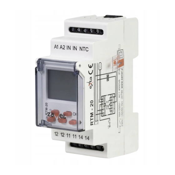
APPEARANCE
● Mounted on TH 35 rail,
● Relay output, 16 A maximum load.
Power terminals
(A1, A2)
The device should be con-
nected to a single-phase
system according to current
standards. The device con-
nections will be described in
this manual. Only qualifi ed
CAUTION
electricians are allowed to
Display
mount, connect and adjust the module. It is
necessary to read this manual before the de-
vice mounting. Do not disassembly the device
casing or you will lose any warranty rights and
expose yourself to the electric shock hazard.
Before mounting operation make sure of di-
Control buttons
sconnecting the connection wires from the
electric network. Use a cross-head screwdri-
ver of 3.5 mm diameter to mount the device.
The regulator should be carried, stored and
used in an appropriate way. Do not mount the
device in case of any regulator parts lack, da-
mage or deformation. In case of malfunction
Relay output terminals
please notify the manufacturer.
(12, 12, 11, 11, 14, 14)
INSTRUCTION MANUAL
DESCRIPTION
Button description
• the main window – entering the automatic op mode;
• ther windows – exit to a higher level without saving changes
entered;
• the main window – entering the manual op mode or the tem-
perature setting changing, if the manual mode set previously;
• other windows - exit to a higher level without saving
changes;
• the main window – entering the main menu;
• other windows – entering a submenu or the set value ac-
knowledgement;
• toggle between menu windows / options or the set value
increase / decrease
o
C
C
o
MAIN MENU
2
o
C
C
o
DATE SETTING
NTC terminals
(NTC)
Trigger terminals
(IN, IN)
VER. 004_31.03.2010
Description of displayed fi elds and messages
From window no.
it is possible to enter the info window (time and date) no.
pressing the cursor
or . The window will be closed after 15 seconds automatically.
Window
Window
,
- relay state
- automatic mode
- relay state
- manual mode
- automatic mode
- output temperature
- manual mode
- non-freeze temperature
- winter time
- comfort temperature
- current date
- econo temperature
- current time
- temperature setting
- actual temperature
Other windows:
- day
- year
- automatic
- user's
- ON/OFF
- NTC probe error (short circuit or break)
.
Enter the menu by pressing OK in the main window;
scroll the menu by means of the following cursors
.
Function
Description
PROGRAM ASSIGNING
TEMPERATURE SETTING
PROGRAM SETTING
CURRENT TIME SETTING
CURRENT DATE SETTING
SUMMER / WINTER TIME SETTING
EXTERNAL OUTPUT SETTING
SENSOR ADAPTATION SETTING
- Current date setting; entry after pressing OK;
YEAR - choose adequate year with cursors
confi rm with OK, range of
years: 2000÷2099;
MONTH - choose month with cursors
confi rm with OK;
DAY - choose day with cursors
confi rm with OK; the system has a protec-
tion against introducing incorrect parameter of a day for a given month ( it
takes into account leap years and it automatically calculates the day of the
week on the basis of an arranged date);
Confi rmation causes movement to a date setting window and set-up of cur-
rent summer/ winter time - if the option
is arranged.
It is possible to exit every sub- menu window in any moment without
saving settings by pressing the button
or .
TIME SETTING
after
- days of week
WINTER / SUMMER TIME SETTING
OPERATING MODE CHANGE (AUTOMATIC, MANUAL)
- setting the current clock time; entry after pressing
OK;
HOUR- choose adequate hour with cursor
which you can
set in 1-24
or 1-12
(AM) and 1-12
(PM)format; confi rm
with OK;
MINUTES - choose adequate parameter of minutes with cur-
sors
confi rm with OK;
Confi rmation of the parameter of minutes causes simultane-
ous nullifi cation of the parameter of seconds and movement to
the window of time setting.
It is possible to exit every sub- menu window in any moment
without saving settings by pressing the button
or .
- choice of one of the two modes in which switching be-
tween winter and summer season time will occur.
- switching
will take place in an automatic way, on the last Sunday of March, at
2.00 (for summer time) and on the last Sunday of October, at 3.00
(for winter time),
- a user chooses between winter/ summer
time, entry after pressing OK;
setting the mode - choose mode
or
with cursors
, confi rm with OK; after choosing the mode
, the clock au-
tomatically sets the time as winter or summer one, depending on
the arranged date; after choosing the mode
you go to another
window;
Choose time for winter/ summer one with cursors
where
is
winter time and
is summer time, if change of marker has hap-
pened the system will change the current time by adding or sub-
tracting 1 hour, confi rm the operation with OK;
After choosing the system moves to winter/ summer time shift win-
dow.
It is possible to exit every sub- menu window in any moment
without saving settings by pressing the button
or .
MANUAL OP MODE TOGGLE - if the main window is open
and the device is in the automatic op mode , pressing the
key
will force the unit to toggle into the manual op
mode with active non-freeze temperature
; succes-
sive pressing the key
will force the manual op mode
changeover as follows:
non-freeze temperature;
comfort temperature;
econo temperature;
output temperature.
If the unit is in one of the mentioned manual op modes
, pressing the key
will force return to the automatic
mode .
Advertisement

Related Manuals for Zamel exta RTM-20


Summary of Contents for Zamel exta RTM-20
- Page 1 Tel. +48 (32) 210 46 65, Fax +48 (32) 210 80 04 the window of time setting. - non-freeze temperature - winter time www.zamelcet.com, e-mail: marketing@zamel.pl - comfort temperature - current date It is possible to exit every sub- menu window in any moment...
- Page 2 4. ZMIE ZAMEL SP. J. is liable for processing any claim according to current Polish legislation. All the display fi elds will light up; 5. ZMIE ZAMEL SP. J. shall process the claim at its own discretion: product repair, replacement or money return. After a while, the clock will automatically set date and time.
- Page 3 Temperature Sensor Modules Click to view products by manufacturer: Zamel Other Similar products are found below : HPP809A031 MBT 3560-0000-0050-10-110 MBT 3560-0000-0100-10-110 MBT 3560-0001-0050-10-120 MBT 3560-0001-0100-10-120 TCN4L-22R TX4H-14R TX4H-24R TX4H-A4R TX4H-B4R TX4L-14R TX4L-A4R TX4L-B4R TX4M-14R TX4M-24R TX4M-A4R TX4M-B4R QP99 CP-02 CP82 CP99 R38-LAOO R38-LARR 72-11304023-0150.0050 72-11304027-0150.0050 72-23304003- 0150.0050.GGP 72-23904001-0300.0040.TM 72-34904001-0300.0040.TM TEM 73 A AT403-414-1000 AT403-614-1000 AT-503-1141-000...
Need help?
Do you have a question about the exta RTM-20 and is the answer not in the manual?
Questions and answers