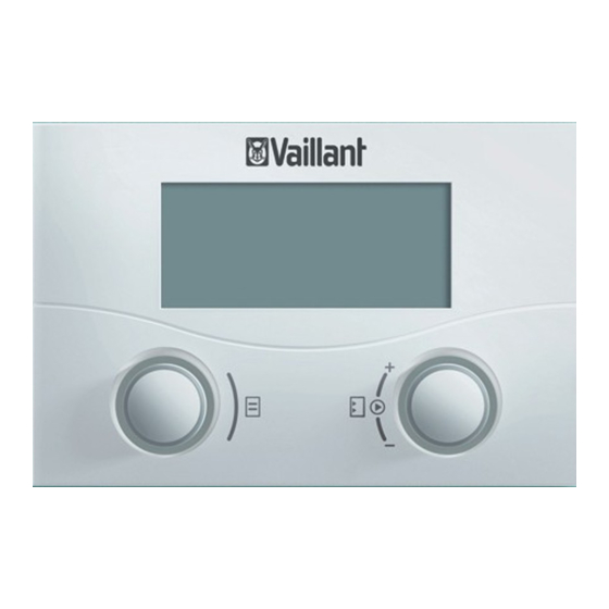
Summary of Contents for Vaillant VR 90
- Page 1 For heating engineer/owner Operating and Installation Manual VR 90 Remote control unit Bus-modular control system VR 90...
- Page 3 For the operator Operating manual VR 90 Remote control unit Bus–modular control system VR 90 Contents Notes on the documentation ......2 Knobs .................4 Other applicable documents ........2 Operator guidance ..........4 Storing the documents ..........2 3.5.1 Menu selection ............4 Symbols used ............2 3.5.2 Tables for the menu level ........4...
- Page 4 Description of the device We accept no liability for any damage caused by non– observe these instructions. The VR 90 remote control unit is used for the individual Other applicable documents setting of a heating circuit within a heating system with auroMATIC 620, VRC 630 or geoTHERM.
- Page 5 Operation Special functions Only possible in the basic display (Saving, Party) All adjustments that need to be made for the connected heating circuit can be carried out using the VR 90 re- Press the knob, to select the special function mote control device.
- Page 6 The VR 90 display varies, depending on the selection ming performed. Sections 3.1 and 3.2 show the basic (basic display, menu displays, displays on the code structure of the display and the operating procedure for level).
- Page 7 The set–back temperature is the temperature to which the heating is regulated Set–back temperature > 15 °C during the set–back period. Heating curve 0,90 > Select target room temperature Table 3.1 Settable parameters Operating and installation manual for remote control unit VR 90 0020055329_01...
- Page 8 In the entire control system there is only one Code which can, if required, be changed in the central controller. 1 0 0 0 > Adjust numeric character Table 3.1 Settable parameters (continued) Operating manual for remote control unit VR 90 0020055329_01...
- Page 9 After 5 seconds the display reverts to the basic display. After the function ends (time expired) or if the knob is pushed again, the basic display shows the original oper- ating mode of the heating circuit again. Operating and installation manual for remote control unit VR 90 0020055329_01...
-
Page 11: Table Of Contents
For the heating engineer Installation instructions VR 90 Remote control device Bus–modular control system VR 90 Contents Notes on the documentation ......2 Setting the Bus address ........5 Other applicable documents ........2 Storing the documents ..........2 Start–up ............5 Applicability of the manual ........2 Setting heating circuit parameters ....5... -
Page 12: Notes On The Documentation
We accept no liability for any damage caused by non–observe these CE mark instructions. The CE mark certifies that the VR 90 remote control unit in conjunction with Vaillant boilers fulfils the basic Other applicable documents requirements of the following directives: When installing the VR 90 remote control unit, observe •... -
Page 13: Safety Instructions And Regulations 2
Installation location At a glance: What you have to do to install the VR 90 Please note that, when selecting the installation loca- remote control unit. -
Page 14: Electrical Installation
It simply has to be ensured that the bus interfaces are eventually connected to the central controller. The structure of the Vaillant system allows you to lay the eBus from component to component. This means that the wires can be swapped without impairing com- munication. -
Page 15: Setting The Bus Address
Heating circuit 3 VRC 630 VR 60, Address 4 HC 4 HC 5 VR 60, Address 6 HC 6 HC 7 VR 60, Address 8 HC 8 Table 4.1 Bus addresses to be set Installation manual Remote control unit VR 90 0020055329_01... - Page 16 0 – 300 minutes Max. preheating 0 min Flow temp. Target 55 °C Flow temp. Actual 45 °C Pump status Mixer status Open > Select Table 5.1 Settings in the Code level Installation manual Remote control unit VR 90 0020055329_01...
-
Page 17: Handing Over The Control To The Owner
• Go through the operating manual with the owner and answer any questions. • Draw special attention to the safety instructions which the owner must follow. • Tell the owner to keep the manuals nearby the con- trol. Installation manual Remote control unit VR 90 0020055329_01... -
Page 18: Overview Of Functions
See more about this in the description of the "Switch on room temp. (systems with cooling function)" function in this table. Table 6.1 Overview of functions Installation manual Remote control unit VR 90 0020055329_01... - Page 19 When the function is ac- tive, the room sensor in this VR 90 is used. Table 6.1 Overview of functions (continued) Installation manual Remote control unit VR 90 0020055329_01...
- Page 20 Represents the inlet temperature in a heating circuit calculated by the controller on the basis of the pre–set parameters. Actual inlet temperature The actual inlet temperature in a heating circuit. Table 6.1 Overview of functions (continued) Installation manual Remote control unit VR 90 0020055329_01...
-
Page 21: Technical Data 7
Maximum permissible ambient temperature °C Minimum cross section of the connection wires 0.75 Dimensions of the wall box Height Width Depth Level of protection IP 30 Protection class for controller Table 7.1 Technical data Installation manual Remote control unit VR 90 0020055329_01... -
Page 22: Warranty And Customer Service
Maintenance Agree- ment. Please contact Vaillant Service Solutions (0870 6060 777) for further details. Recycling and disposal Both the Vaillant VR 90 remote control unit and its as- sociated transport packaging consist predominantly of recyclable raw materials. Unit As with all accessories, the Vaillant VR 90 remote con- trol unit has no place in the household waste.


Need help?
Do you have a question about the VR 90 and is the answer not in the manual?
Questions and answers