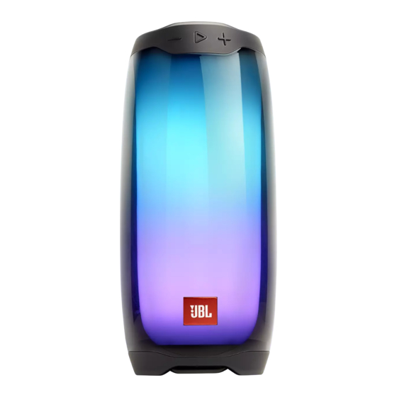
Summary of Contents for JBL PULSE 4
-
Page 1: Table Of Contents
(S/N starting from ND) PULSE 4 SKU: JBLPULSE4BLK、JBLPULSE4WHT、JBLPULSE4BLKAM、JBLPULSE4WHTAM CONTENTS TECHNICAL SPECIFICATIONS SCHEMATIC DIAGRAMS LAYOUT DIAGRAMS SAFETY SHEET BLOCK DIAGRAM EXPLODED VIEW WIRING DIAGRAM PARTS LIST HOW TO DISASSEMBLE REVISION LIST Released by Global Quality Ver. 1.0 Jul 2019 harman/kardon, Inc. -
Page 2: Technical Specifications
TECHNICAL SPECIFICATIONS · Model Name: JBLPULSE4 · Bluetooth version: 4.2 · Support: A2DP V1.3, AVRCP V1.6 · Transducer: 2.25 inch · Rated power: 20 W RMS · Frequency response: 70 Hz - 20 kHz · Signal-to-noise ratio: >80 dB · Battery type: Lithium-ion polymer 26 WH (Equivalent to ·... -
Page 3: Safety Sheet
harman/kardon Important Safety Instructions 1. Read these instructions. CAUTION 2. Keep these instructions. 3. Heed all warnings. RISK OF ELECTRIC SHOCK. DO NOT OPEN. 4. Follow all instructions. 5. Do not use this apparatus near water. 6. Clean only with a dry cloth. 7. - Page 4 Some semiconductor (solid state) devices can be damaged easily by static electricity. Such components commonly are called Electrostatically Sensitive (ES) Devices. Examples of typical ES devices are integrated circuits and some field effect transistors and semiconductor "chip" components. The following techniques should be used to help reduce the incidence of component damage caused by static electricity. 1.
- Page 5 SAFETY PRECAUTIONS The following check should be performed for the continued protection of the customer and service technician. LEAKAGE CURRENT CHECK Measure leakage current to a known earth ground (water pipe, conduit, etc.) by connecting a leakage current tester between the earth ground and all exposed metal parts of the appliance (input/output terminals, screwheads, metal overlays, control shaft, etc.).
-
Page 6: Block Diagram
JBL PULSE 4 BLOCK DIAGRAM OP 1PCS RGB LEDs Mix/Mono TPA2412/NJM2740/B TPA3128 (with drivers) A4510 25W PBTL 26dB SPI_MOSI1 OP 1PCS 3ohm BUFFER TPA2412/NJM2740/ SGM7SZ125 25wX1 /SD103 BA4510 Boost control USB Detect Logic Power_ON_OFF 4MB Flash STM32F401CCU6 SLG4V4826V Power button UART BT Module... -
Page 7: Wiring Diagram
3.8V for RGB LEDs MP28164 LDO-3.3V SLG_3.3V ME6211 BOOST LDO-3.3V OP_3.3V 3.6V SYV709 ME6211 BOOST_EN LDO-3.3V SCALE: FREE MODEL: JBL PULSE 4 BLOCK VDD_FEM REV: ADD NTC SHEET: 1/1 FEM_LDO_EN ME6211 Part NO: APPROVAL CHECKED DESIGN TIGER ANDY 3NOD DIGITAL 4.29/2019... -
Page 8: How To Disassemble
Disassembly Instruction (May refer to related video) Disassemble the USB PCBA Move away the silicone BT Move away the top cap with “_” Move away the silicone Take away the top cap type screwdriver button power button Move away IO cover Tear down the bottom cover... - Page 9 Move away screws USB PCBA Move away the connected bracket Disassemble the LED Push the inner body Move away Inner barrel away from the out barrel Out barrel screws from speaker upper bracket.
- Page 10 Move away the speaker upper bracket from the inner body Disassemble the Main PCBA and BT PCBA Main PCBA BT PCBA...
-
Page 11: Schematic Diagrams
VSYS: 3.5~4.75V USB+5V_IN Ioff ILMAX=3A FB330 Li-bat: <=15uA BQ25601D EMC ADD 1.5uH/10A CON3 3.9~13.5V CON1 CON5X2B USB_5V VBUS BAT- NTC1 FB330 100P 680P PMID BTST 10u/16V NTC2 NTC2_TMP NTC1_CHG VBAT_1 3.3V STAT SYS2 BAT+ SYS1 FB330 STAT SCL1 VBAT_1 BAT2 SDA1 BAT1 4.7u/10V... - Page 12 [1,2] 10PF [1,2] C198 VDD_FEM BOOST_BYPASS_EN ANT1 1 VIN 3.6V VOUT AMT4 POWER_LED 4.7K 4148W 3 CE 4.7U 103P R195 FEM_LDO_EN AMP_MUTE GPIO6 ME6212_3.3V 2N3906 [1,2] 4.7U VDD_FEM VDD_FEM C170 [1,2] To MCU UART USBVCCA33 100K GPIO4 MODSEL 1 GPIO4/UART0_CTS USB+5V_IN [1,2] R190...
- Page 13 AMP_SD VBAT_1 VOUT SLG_3.3V VDD_FEM [1,2] 4 NC FB120 MCU_3.3V M_3.3V ME6212_3.3V [1,2] 4.7U 4.7u/10V MCU_3.3V [1,2] R217 [1,2] R209 R207 100R VBAT-1 LINK_LED VBAT_O SCL1 [1,2] R208 ME2333 ME2333 SDA1 [1,2] B5819 4.7K 4.7K VBAT_1 USB+5V_IN R210 R212 100K R206 MCU_3.3V RGB_LED_POWER_EN...
- Page 14 LIGHT for MCU pcb for MCU pcb for MCU pcb LIGHT_KEY PLAY_KEY SLG_3.3V B_LED LINK_KEY VOL+_KEY BT_KEY LINK L_LED VOL-_KEY SLG_3.3V POWER_KEY POWER P_LED POWER KEY FPC LIGHT KEY FPC VOL KEY FPC...
- Page 15 DOUT...
- Page 16 6 LEDs for battery energy ind. White Input Voltage: 4.75~5.25V 100R BT & MCU upgrading White CON12 100R CON_SMT_12 White 100P 100R 100P 100P White 100P 100R 100P White 100P 100R 100P 100R USB Board for MCU pcb 0/1206 GND4 GND2 RX1+ Type C Port...
-
Page 17: Layout Diagrams
6.Layout Diagrams... -
Page 28: Exploded View
MECHANICAL EXPLODED VIEW Pos. No. Description UoM Usage A1+A2+A3+A4+ 32200962 TOP CAP ASSY BLK PULSE4 A5+A6+A45 A1+A2+A3+A4+ 32200963 TOP CAP WHT ASSY PULSE4 A5+A6+A45 A10+A41+A43 32200967 INNER BUTTON ASSY PULSE4 31103501 SPEAKER UPPER BRACKET PULSE4 31601875 VOLUME CONTROL BOARD PULSE4 31103502 SPEAKER MIDDLE BRACKET PULSE4 31103504 LED UNDER BRACKET PULSE4 31300914 INNER BARREL PULSE4... -
Page 29: Parts List
JBL Pulse 4 ND Spare Parts List v1.0 Pos. No. Description UoM Usage A1+A2+A3+A4+ 32200962 TOP CAP ASSY BLK PULSE4 ND A5+A6+A45 A1+A2+A3+A4+ 32200963 TOP CAP WHT ASSY PULSE4 ND A5+A6+A45 A10+A41+A43 32200967 INNER BUTTON ASSY PULSE4 ND 31103501 SPEAKER UPPER BRACKET PULSE4 ND... -
Page 30: Revision List
Revision List Version 1.0 * Initial release. 2019-08...


Need help?
Do you have a question about the PULSE 4 and is the answer not in the manual?
Questions and answers
Se quebraron dos patitas en la placa que va unida **** la otra no puedo armar mi pulse 4 necesito un taller autorizado ayúdenme vivo en Concord California
Se quebraron 2 patitas que van en una de las 2 placas que van unidad no puedo armar mi jbl vivo en Concord California