Advertisement
Quick Links
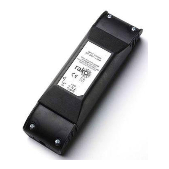
Rako RLED Series Dimmable LED Driver Modules – Installation, Programming and Operating Instructions.
The Rako RLED series of modules provide constant
current dimmable output suitable for use with
350mA, 600mA and 700mA LED modules.
Input supply is direct from 230v ac supply.
Brightness is controlled by Rako scene-sender
panels transmitting Rakom encoded radio signals.
Fixing Screws
Terminal
Cover
Protective
Insert
Supply/Load
Terminals
Fig 1.
Front View of Components
Installation
Before commencing installation of a Rako dimmer
module first read this instruction manual carefully.
Rako Controls Ltd accepts no responsibility for any
damage or injury caused by incorrect installation of
a Rako product.
Installation should only be carried out by a
competent electrician.
Never attempt to connect a Rako dimmer or
remove the terminal covers without first isolating
the circuit at the fuse/MCB board.
The circuit supplying a Rako dimmer should always
be protected by either a 5A fuse or 6A MCB.
Rako RD dimmer modules should be mounted in
areas that are adequately ventilated, dry and
outside of any enclosed metal casings. Wherever
possible the modules should be securely fixed using
the mounting holes provided. The mounting holes
are blanked off when supplied but are designed so
that a woodscrew will easily cut through without
the need for drilling.
Whilst the Rako dimmer modules are designed to
be completely maintenance free the units should
be mounted in a position where access can be
gained should there be a fault or re-addressing of
the unit be necessary (see 'Set-up and
Addressing').
Permissible loading.
350mA, 600mA or 700mA maximum output selectable
by jumper.
Maximum output voltage is 30V DC.
For 1W White LED's. Maximum loading = 9 x LED in
series. Set Jumper to 350mA setting.
Jumper A OFF, Jumper B OFF.
For 2W White LED's. Maximum loading = 9 x LED in
series. Set Jumper to 600mA setting.
Jumper A ON, Jumper B OFF.
For 3W White LED's. Maximum loading = 6 x LED in
series. Set jumper to 700mA setting.
Jumper A ON, Jumper B ON
LED Load
Clamping
Connection
Bar
terminals
A
B
Mounting
Holes
Output current
select Jumpers
A
B
To ensure that the cable clamping operates
satisfactorily the cabling both supplying the dimmer
and to the load should be a minimum of 0.5mm
double safety insulation and the wires should be
stripped to ensure that the cable bar within the
terminal cover clamps firmly on both sets of
insulation.
To install a Rako dimmer module isolate the supply
then remove the Terminal Covers (see Fig.1) giving
access to the supply/load terminals. The necessary
connections are indicated on the label on the dimmer
housing. The notation is as follows:
L –Live wire from the supply (normally coloured
Brown)
N –Neutral (normally coloured Blue)
Once the supply and load cables are connected ensure
that the terminal covers are replaced and securely
fastened, clamping the cable correctly as detailed
above, before powering the unit.
Rako dimmer modules are not designed for loop
in/loop out connections. Should it be necessary to
loop the supply on to further fittings then a junction
box should be connected in circuit to facilitate this.
With the supply and load connected and prior to
switching on the supply ensure that the terminal
covers are fitted and that they are securely clamping
the cables. It is important to ensure that the
protective inserts (see Fig.1) are fitted and located
securely, both in the terminal cover and over the
supply and load cables. The protective inserts provide
important protection against the risk of electric shock
from conductive objects forced down the side of the
cables.
230v AC
Connection
terminals
Set-up and Addressing
Before any lighting scenes can be programmed (see
the wall panel or handheld instruction manual) the
receivers need to be addressed.
To avoid interference between rooms or neighbouring
installations a Rako system should be set to an
address other than the factory default of House 1
Room 4. The preferred addressing method is to select
a logical House address number for the project,
separate Room addresses for each room within the
house and then sequential Channel numbers for each
receiver within each room (see Fig.5) i.e. Channel 1
for the 1
st
receiver, Channel 2 for the 2
House and Room addresses are set using the DIP
switches on the back of a Rako controller (see Fig.4)
and the Channel address is set by 'stepping' through
the channel numbers with a panel in programming
mode (see Step 3 overleaf) and then sending this
number (along with the House and Room address) to
a receiver (Step 5).
2
with
Setting the address switches.
Each Rako transmitter has two, 8 way banks of
switches for setting its address.
switches allow the user to choose from 256 house
addresses and 256 room addresses.
address, unclip the rear cover whereupon the banks of
switches will be now become visible.
address, use a small terminal screwdriver or similar
device and carefully move some of the switches into
the 'ON' position. Addressing uses binary encoding
and the value of the switches is shown below.
Note: Any control panels set with the same address
will act as two or multi way controls.
128
64
32
16
8
4
2
1
House address
= 128+16=144
Addressing Switches
Channel 2
House 144
Room 5
Channel 1
nd
etc. The
Addressing Example
Notes on addressing.
A dimmer will not receive an address of House 0 (All
switches set to off)
A dimmer will respond to, but not receive an address
of Room 0 (All switches set to off). This Room 0
address is used for 'Master House' control
A dimmer cannot be set to channel 0.
To program a lighting scene see Wall panel or Hand
held manual.
The two sets of
Care and maintenance
To set the
A Rako dimmer module contains no user serviceable
To set an
parts. Should for any reason you need to contact us
please contact us via our website
www.rakocontrols.com or by phoning our customer
help line on 01634 226666.
128
64
32
16
8
4
2
1
Room address
= 32+4=36.
Fig 4.
Channel 2
House 144
Room 6
Channel 1
144
Fig 5.
Advertisement

Related Manuals for rako RLED Series


Summary of Contents for rako RLED Series
- Page 1 Rako RLED Series Dimmable LED Driver Modules – Installation, Programming and Operating Instructions. Note: Any control panels set with the same address The Rako RLED series of modules provide constant Once the supply and load cables are connected ensure will act as two or multi way controls.
Need help?
Do you have a question about the RLED Series and is the answer not in the manual?
Questions and answers