Table of Contents
Advertisement
Quick Links
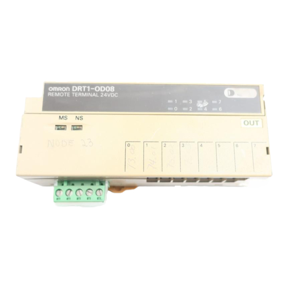
Transistor Remote Terminal
Compact 8-point and 16-point
Transistorized Terminals
Compact
(8-point models: 125 x 40 x 50 mm (W x H x D);
16-point models: 150 x 40 x 50 mm (W x H x D))
Two independent power supplies can be used
because the I/O terminals are insulated from the
internal circuits.
DIN track mounting and screw mounting are
available.
Ordering Information
I/O classification
Internal I/O
circuit common
Input
NPN (+ common)
Output
NPN (– common)
Input
NPN (+ common)
Output
NPN (– common)
Specifications
Ratings
Input
Item
Input current
ON delay time
OFF delay time
ON voltage
OFF voltage
OFF current
Insulation method
Input indicators
Output
Item
Rated output current
Residual voltage
Leakage current
Insulation method
Output indicators
Note: Do not connect the DRT1-OD16 to loads consuming a total current exceeding 2.4 A.
I/O points
Terminal
8
Screw terminal
16
10 mA max./point
1.5 ms max.
1.5 ms max.
15 VDC min. between each input terminal and V
5 VDC max. between each input terminal and V
1 mA max.
Photocoupler
LED (yellow)
0.3 A/point (see note)
1.2 V max.
0.1 mA max.
Photocoupler
LED (yellow)
DRT1-ID/OD
Rated voltage
I/O rated voltage
24 VDC
24 VDC
DRT1-IDjj
DRT1-ODjj
Model
DRT1-ID08
DRT1-OD08
DRT1-ID16
DRT1-OD16
Advertisement
Table of Contents

Related Manuals for Omron DRT1-ID


Summary of Contents for Omron DRT1-ID
- Page 1 Transistor Remote Terminal DRT1-ID/OD Compact 8-point and 16-point Transistorized Terminals Compact (8-point models: 125 x 40 x 50 mm (W x H x D); 16-point models: 150 x 40 x 50 mm (W x H x D)) Two independent power supplies can be used because the I/O terminals are insulated from the internal circuits.
- Page 2 DRT1-ID/OD DRT1-ID/OD Characteristics Communications power supply 11 to 25 VDC (supplied from the communications connector) voltage +10% Internal power supply voltage 24 VDC –15% +10% I/O power supply voltage 24 VDC –15% Current consumption (see note) Communications: 60 mA max. at 24 VDC Internal circuit: 60 mA max.
- Page 3 DRT1-ID/OD DRT1-ID/OD Indicators Indicator Display Color Meaning Green The Unit is normal. Flashes No node number has been set. The Unit has a fatal error. Flashes The Unit has a nonfatal error. Not lit No power is supplied to the Unit.
- Page 4 DRT1-ID/OD DRT1-ID/OD Node Number Settings Node Pin 6 Pin 5 Pin 4 Pin 3 Pin 2 Pin 1 Node Pin 6 Pin 5 Pin 4 Pin 3 Pin 2 Pin 1 number number Note: The node number is factory-set to 0.
- Page 5 DRT1-ID/OD DRT1-ID/OD Dimensions Note: All units are in millimeters unless otherwise indicated. DRT1-ID08 Mounting Holes DRT1-OD08 125 max. Two, 4.2 dia. or M4 50 max. Fourteen, M3 40 max. DRT1-ID16 DRT1-OD16 Mounting Holes Two, 4.2 dia. or M4 150 max.
- Page 6 DRT1-ID/OD DRT1-ID/OD Installation Internal Circuit Configuration DRT1-ID08 DRT1-ID16 Photo- Photo- 24 VDC coupler coupler 24 VDC Physi- Photo- Communications cal lay- coupler connector Photo- coupler Input terminals 24 VDC DC–DC Power supply for converter internal circuitry (insulated) 24 VDC DRT1-OD08...
- Page 7 DRT1-ID/OD DRT1-ID/OD Terminal Arrangement and I/O Device Connection Example Input DRT1-ID08 DRT1-ID16 Internal I/O power Internal I/O power circuit supply circuit supply power power supply supply Photoelectric sensor or Limit switch Photoelectric sensor or Limit switch proximity sensor (three- (two-wired...
- Page 8 Unit may malfunction. NOTE: ALL DIMENSIONS SHOWN ARE IN MILLIMETERS. TO CONVERT MILLIMETERS TO INCHES DIVIDE BY 25.4. Omron Europe B.V. EMA-ISD, tel:+31 23 5681390, fax:+31 23 5681397, http://www.eu.omron.com/ema Specifications subject to change without notice.
Need help?
Do you have a question about the DRT1-ID and is the answer not in the manual?
Questions and answers