Advertisement
Quick Links
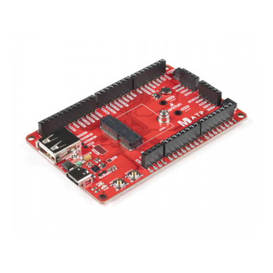
MicroMod All The Pins (ATP) Carrier Board
Introduction
Access All The Pins (i.e. ATP) of the MicroMod Processor Board with the MicroMod ATP Carrier Board!
SparkFun MicroMod ATP Carrier Board
DEV-16885
Required Materials
To follow along with this tutorial, you will need the following materials. You may not need everything though
depending on what you have. Add it to your cart, read through the guide, and adjust the cart as necessary.
MicroMod Processor Board
You'll need a Processor Board to break out the pins.
Advertisement

Related Manuals for sparkfun DEV-16885


Summary of Contents for sparkfun DEV-16885
- Page 1 MicroMod All The Pins (ATP) Carrier Board Introduction Access All The Pins (i.e. ATP) of the MicroMod Processor Board with the MicroMod ATP Carrier Board! SparkFun MicroMod ATP Carrier Board DEV-16885 Required Materials To follow along with this tutorial, you will need the following materials. You may not need everything though depending on what you have.
- Page 2 SparkFun MicroMod Artemis Processor SparkFun MicroMod ESP32 Processor DEV-16401 WRL-16781 SparkFun MicroMod SAMD51 Processor DEV-16791 Accessories At a minimum, you will need a USB C cable to power and program the boards. Depending on your application, you may want to grab a Qwiic cable to connect a Qwiic-enabled device.
-
Page 3: Hardware Overview
SparkFun Mini Screwdriver TOL-09146 Suggested Reading If you aren't familiar with the MicroMod ecosystem, we recommend reading here for an overview. We recommend reading here for an overview if you decide to take advantage of the Qwiic connector. MicroMod Ecosystem Qwiic Connect System If you aren’t familiar with the following concepts, we also recommend checking out these tutorials before... - Page 4 Power There are a variety of power and power-related nets broken out to female header pins and their corresponding through hole pads. The image below highlights those female headers and pads. The board can be powered from the VIN pin with a recommended voltage between 3.3V to 6.0V. It can also be powered with 5V from the USB C connector.
- Page 5 All the [GPIO] Pins Remember our "All the Pins!" nickname? Well, we meant it. On the MicroMod ATP, not only have we broken out all the major pins with female headers, we've added a secondary rail of plated through-holes alongside them to give you the choice of either plug and play or soldering directly to the board.
- Page 6 SWD Programming Pins For advanced users, we broke out the SWD programming pins. Note that this is not populated so you will need a compatible header and compatible JTAG programmer to connect. Jumper Pads There are a few jumpers populated on the board: Bypass (BYP) - By default, the BYP is left open.
- Page 7 General MicroMod Pinout Wondering what the pins are that are broken out on the ATP MicroMod ATP Carrier Board? Check out the table from the Getting Started with MicroMod for more information. Remember to check out the pins against your Processor Board to determine what pins are available.
- Page 8 SPI COPI1 SDIO_CMD SPI_CIPO (I/O) SPI SCK1 SDIO_SCK (O) SPI_COPI (O) LED_DAT AUD_MCLK SPI_SCK (O) LED_CLK PCM_OUT / I2S_OUT AUD_OUT SPI_CS# CAM_MCLK PCM_IN / I2S_IN AUD_IN I2C_SCL1 CAM_PCLK (I/O) PCM_SYNC I2S_WS AUD_LRCLK I2C_SDA1 (I/O) PDM_DATA PCM_CLK / I2S_SCK AUD_BCLK BATT_VIN / 3 PDM_CLK (I - ADC) (0 / 3.3V)
-
Page 9: Hardware Hookup
CAM_TRIG UART_RX1 (0) I2C_INT# UART_CTS1 I2C_SCL (I/0)) UART_RTS1 I2C_SDA (I/0) BOOT (I - Open Drain) USB_VIN RESET# (I - USB_D- Open Drain) 3.3V_EN USB_D+ 3.3V Board Dimensions The board is 3.30"x2.20". There are 4x mounting holes on each corner of the board. Hardware Hookup If you have not already, make sure to check out the Getting Started with MicroMod: Hardware Hookup for information on inserting your Processor Board to your Carrier Board. - Page 10 Getting Started with MicroMod OCTOBER 21, 2020 Dive into the world of MicroMod - a compact interface to connect a microcontroller to various peripherals via the M.2 Connector! At a minimum, your setup should look like the image below. In this case, we had the MicroMod SAMD51 Processor Board secured in the M.2 connector.
- Page 11 To secure the boards together, you could add standoffs and screws to mount a Qwiic-enabled device that have the standard 1.0"x1.0" sized board. Keep in mind that this will block a few of the header pins below so make sure to plan accordingly.
- Page 12 Now that you have a Processor Board secure in the Carrier Board, let's upload a simple blink sketch to the board. Copy and paste the following code in the Arduino IDE. Head to Tools > Board to select the correct board definition (in this case, SparkFun MicroMod SAMD51. Select the correct COM port that the board enumerated to. Hit upload.
-
Page 13: Troubleshooting
SPARKFUN TECHNICAL ASSISTANCE PAGE If you don't find what you need there, the SparkFun Forums are a great place to find and ask for help. If this is your first visit, you'll need to create a Forum Account to search product forums and post questions. - Page 14 MicroMod ESP32 Processor Board Hookup Guide Guide This tutorial covers the basic functionality of the A short Hookup Guide to get started with the SparkFun MicroMod SAMD51 and highlights the features of the MicroMod ESP32 Processor Board ARM Cortex-M4F development board.
Need help?
Do you have a question about the DEV-16885 and is the answer not in the manual?
Questions and answers