Table of Contents
Advertisement
Quick Links
micro:bot Kit Experiment Guide
Introducing the micro:bot Kit
The micro:bit is a great platform for learning how to build and program robots! Combining the micro:bit with the
SparkFun moto:bit - micro:bit Carrier Board (Qwiic) creates a flexible, low-cost robotics platform for anyone from
students getting started with the micro:bit to the engineer looking to quickly prototype or build a proof of concept.
The micro:bot kit v2.0 is the extension of that idea: build simple robots quickly that leverage the capabilities of the
micro:bit while implementing peripheral sensors and motor functions with simple programming in the Microsoft
MakeCode environment as a gateway into robotics.
Product Showcase: SparkFun micro:bot kit v2.0
Product Showcase: SparkFun micro:bot kit v2.0
What's Included in the Kit?
Advertisement
Table of Contents
Troubleshooting

Related Manuals for sparkfun micro:bot Kit


Summary of Contents for sparkfun micro:bot Kit
- Page 1 The micro:bot kit v2.0 is the extension of that idea: build simple robots quickly that leverage the capabilities of the micro:bit while implementing peripheral sensors and motor functions with simple programming in the Microsoft MakeCode environment as a gateway into robotics.
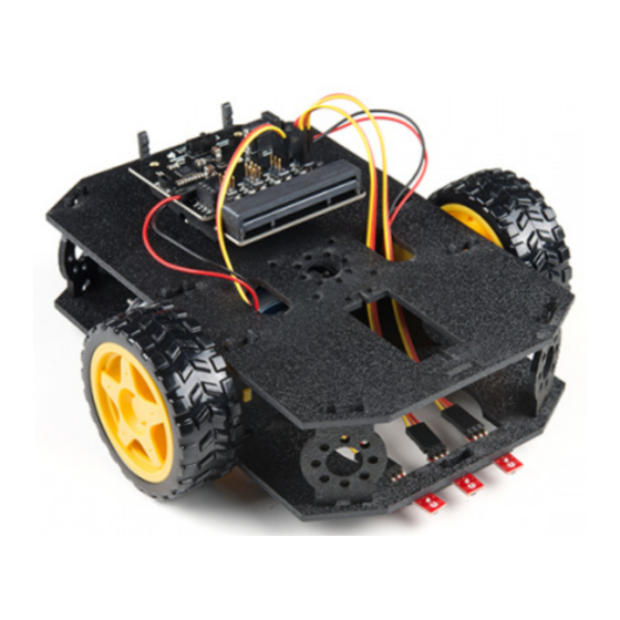
- Page 2 SparkFun micro:bot kit for micro:bit - v2.0 KIT-16275 The kit includes the following parts: 1x SparkFun moto:bit (Qwiic) - Carrier board multiple I/O pins capable of hooking up servos, sensors and other circuits. 1x Shadow Chassis - Our go to robotics chassis for tabletop robotics.
-
Page 3: Suggested Reading
How to Use This Guide? This guide is designed to get you started with the moto:bit board and the SparkFun micro:bot kit in a straight forward and simple way. We demonstrate each component's functionality and the corresponding code to make it work. -
Page 4: Open Source
The moto:bit is a carrier board for the micro:bit. Similar to an Arudino shield, it is designed to add functionality to the micro:bit without the hassle of a number of other boards, soldering, and all of those jumper wires. SparkFun moto:bit - micro:bit Carrier Board (Qwiic) DEV-15713 In this case, the moto:bit takes a micro:bit and turns it into a full blown robotics platform. -
Page 5: Edge Connector
Control servo motors I C port for extending functionality That is a lot of options in terms of bells and whistles! Let's take a closer look at the board and go over each section. Note: If you have the previous version of this board (DEV-14213), note that the functionality is, for all intents and purposes, the same. - Page 6 H-Bridge and Motor Pins An H-Bridge is a chip that is the heart of a robot when it comes to driving motors and more specifically driving motors in both directions. Depending on the electrical state of specific pins on the H-Bridge, a motor drives forwards, backwards, and at different speeds.
- Page 7 chassis, and the way the motors are wired to the input pins. Motor Control Switch The moto:bit has a switch that controls the power supply to the motors. That way you can have the robot powered while working on it or programming it and know that the robot is not going to start moving and drive off of the table. Believe us...
- Page 8 We have a number of sensors and actuators that are built in this pin formation and will work with this board. SparkFun Line Follower Array Wheel Encoder Kit SEN-13582 ROB-12629 SparkFun RedBot Sensor - Mechanical Bumper SparkFun RedBot Buzzer SEN-11999 ROB-12567...
- Page 9 SparkFun RedBot Sensor - Accelerometer SEN-12589 Servo Ports No robot is complete without an arm, a swiveling "head," or some other type of movement other than wheels. Notice that a couple of the pin groups are designated as "Servo". You can connect servo motors directly to these pins and use them right out of the box with Microsoft MakeCode.
- Page 10 Qwiic Connector With the updated moto:bit board, we've added a Qwiic connector so that our Qwiic line of products can be incorporated more easily. Power A standard barrel jack connector is used for easily powering your robot. We find that a 4xAA battery pack works great, but it will accept between 3V-11V at the barrel jack.
- Page 11 This section will cover how to assemble your robot chassis. Assembly time: 30-60 minutes The robot chassis requires the following pieces to build. You'll find most of them in your SparkFun micro:bot kit. Note: Several of the parts need to be snapped out of the main chassis panels.
- Page 12 Click on the image for a closer look. Letter Part Bottom Chassis Plate Top Chassis Plate Front Motor Mount Rear Motor Mount Side Strut Encoder Mount (Not Used in this Guide) moto:bit Mount Battery Pack Clip Line Follower Mount Line Follower Mount Plate Jumper Wire —...
- Page 13 When we talk about the "front," "left," "right," and "back" of the Shadow Chassis, we are referring to specific sides of the robot when viewed from above. Notice that we consider the SparkFun moto:bit to be on the "back" of the bot and the Bumper Whiskers and Line Follower Boards to be in the "front."...
- Page 14 Attach Rear Motor Mounts Hold the wires near the middle of the Motor (N), and carefully slide a Rear Motor Mount (D) in from the side and over the two motor wires. Be careful not to snag the wires, the cable tie, or the clear plastic strap. Holding the motor wires, gently twist the Rear Motor Mount counter clockwise so that it snaps in place on the motor and the wires are centered in the gap of the motor mount.
-
Page 15: Attach The Wheels
Repeat the process for the second motor. Attach the Motor Assemblies to the Chassis Snap one of the motor assemblies into the left two horizontal slots of the Bottom Chassis Plate (A). Make sure that the rounded edges of the motor mounts and the wires are facing toward the center of the chassis. Repeat for the opposite motor. - Page 16 Repeat with the other wheel. Installing the Line Sensors This section will cover the Line Following Sensors array assembly. You'll first build the Line Following array and then attach it to the chassis. Locate the following: Construct the Line Follower Assembly Attach the three Line Follower Boards (O) to the Line Follower Mount (I) such that the rectangular pegs in the Line Follower Mount poke through the mounting holes in the Line Follower Boards.
-
Page 17: Attach The Cables
Place the Line Follower Mount Plate (J) on top of the Line Follower Mount (I) so that the center clip of the mount is poking through the center slot of the plate. Attach the Cables You will need to connect a 3-Wire Jumper Cable (K) to each of the Line Follower Boards (O). Note the color of the wire attached to each pin. -
Page 18: Final Assembly
Attach the Line Follower Assembly to the Chassis Locate the wide, rectangular slot near the front of the chassis and snap the line follower assembly in from the bottom side of the chassis. Route the cables through the large hole in the bottom plate. The bottom of your chassis should look like the following image allowing the line sensors to be facing down. - Page 19 You will also need the Top Chassis Plate and Bottom Chassis Plate assemblies, which have any additional parts and sensors you attached in previous steps. Attach the Nub Caster Snap the Nub Caster (M) into the slot on the back of the Bottom Chassis Plate assembly. Make sure the Nub Caster is on the side opposite the motors (the bottom side).
- Page 20 Route the Cables Position the Top Chassis Plate over the Bottom Chassis Plate -- but do not snap the two plates together yet. Make sure that the front sides of each plate line up. Route the wires and cables through the left and right oval slots in the Top Chassis Plate assembly as shown. For the center line follower sensor, route this cable through the left oval slot.
- Page 21 Attaching the moto:bit In this section, you will add brains of the robot: the micro:bit and SparkFun moto:bit. Locate the following: You will also need the full chassis assembly, which contains any additional parts you attached in previous steps.
- Page 22 Push gently and evenly until it snaps into place. Note: The other slots in the moto:bit mounts can be used to hold the Arduino Uno or the Sparkfun RedBoard. Once snapped, your setup should look like the image below without the wires connected to the moto:bit board...
-
Page 23: Connecting The Cables
Connecting the Cables It is time to connect the jumper wires; it is really important that these connections are right. Follow along with the tables and annotated image with the cables connected for reference. Trace each cable poking through the top chassis plate to make sure you know what it is connected to. Please Note: When you have the micro:bot upright and the front of the chassis facing away from you, "left"... - Page 24 Left Line Follower: SparkFun moto:bit Pins Jumper Wires Left Line Follower Board 3-Wire Jumper Cable - Yellow 3.3V 3-Wire Jumper Cable - Orange 3-Wire Jumper Cable - Red Center Line Follower: SparkFun moto:bit Pins Jumper Wires Center Line Follower Board 3-Wire Jumper Cable - Yellow 3.3V...
- Page 25 Make sure to follow the color of the wire with the silkscreen on the board. Below is a table for each connection between moto:bit and motor. Left Motor: SparkFun moto:bit Pins Left Motor Jumper Wires LEFT MOTOR - RED...
- Page 26 Warning! So what happens when you wire the motors the other way? Well, your motor may move a different direction when using the example code provided in this tutorial. There are two options if you notice the micro:bot moving in the wrong direction. You can flip the wiring of your motors or use the adjust the code blocks to change what is forward vs reverse.
-
Page 27: Insert Batteries
Insert Batteries Insert the AA batteries into the Battery Holder (P). Makes sure the batteries are facing the correct direction, as per the markings inside of the Battery Holder. Attach Battery Pack Insert the Battery Holder (P) with batteries into the back cavity of the chassis. Position the Battery Holder so that the barrel jack cable comes out on the left side of the robot. -
Page 28: Changing The Batteries
Push the clip down into the vertical slots in the Bottom Chassis Plate so it snaps in place. Route the barrel jack cable out of the left side of the chassis and up to the moto:bit. Plug the barrel jack cable into the barrel connector on the side of the moto:bit carrier board. Changing the Batteries... - Page 29 If you find that you need to replace the batteries in the micro:bot, the process is simple. Unplug the battery pack from the moto:bit. Turn the micro:bot over and push on the Battery Holder through the hole in the Bottom Chassis Plate. This will cause the Battery Pack Clip to unsnap from the Bottom Chassis Plate.
- Page 30 "Add Extensions." This should be the last item on the list. From here you can search for "SparkFun" or "SparkFun moto-bit," and it should show up as a public extension in the list. Go ahead and click on it.
-
Page 31: Parts Needed
Great! You have now installed the moto:bit extension and are ready to use the board as well as the components that come in the micro:bot kit. As a side note, for every new MakeCode project that you make, you will have to load extensions over again. - Page 32 Hobby Gearmotor - 140 RPM (Pair) USB micro-B Cable - 6 Foot ROB-13302 CAB-10215 micro:bit Board SparkFun moto:bit DEV-14208 DEV-14213 Wheel - 65mm (Rubber Tire, Pair) Battery Holder - 4xAA to Barrel Jack Connector ROB-13259...
- Page 33 Shadow Chassis Panasonic Alkaline Battery - AA ROB-13301 PRT-15201 Suggested Reading Before continuing on with this experiment, we recommend you be familiar with the concepts in the following tutorial: Motors and Selecting the Right One Getting Started with the micro:bit Learn all about different kinds of motors and how they The BBC micro:bit is a compact, powerful programming operate.
-
Page 34: Hardware Hookup
The hobby motors used with the micro:bot operate in a similar was as mentioned above, but they have a bit of help; a gear box. The ratio of the gearbox is 120:1, which means that for every 120 rotations of the motor shaft you get one rotation at the end of the gear box. - Page 35 Why is that? Well, in robotics the right and left motors are mirrors of one another, which means they go in opposite directions from one another to go forward, hence the ports being backwards. If you plug them in as the same direction and tell both motors to spin in the sam direction, your robot would spin in a circle rather than drive forward! Weird, but true.
- Page 36 move left motor motor forward Code to Note Let's take a look at the code and what to expect. On Start The code starts by setting each motor channel in the code block. Depending on how the motors are on start wired to the moto:bit, your micro:bot may drive in the opposite direction than what you would expect.
- Page 37 "RUN MOTORS." Press the A button on your micro:bit and your robot will drive forward for 1 second, pivot, and the drive forward for another second before stopping. Pressing the button again will have the robot repeat the sequence. Here is a demo of the micro:bot driving. micro:bot micro:bot kit: Exp1 kit: Exp1...
-
Page 38: Troubleshooting
But wait? The micro:bot appears to be driving in the reverse relative to the front of the robot even though we told the robot to move in the code?!? There are a few reasons why this may be happening. Depending on forward how the motors were manufactured, they wires may be switched. - Page 39 micro:Bot Not Driving in a Straight Line - Try adjusting left or right motor's % to calibrate. Moving in Reverse?! - There are two options if you notice the micro:bot moving in the wrong direction. As explained above, you can flip the wiring of your motors or use the block in set ____ motor invert to ____ your...
- Page 40 DEV-14213 Wheel - 65mm (Rubber Tire, Pair) Battery Holder - 4xAA to Barrel Jack Connector ROB-13259 PRT-09835 SparkFun RedBot Sensor - Line Follower Shadow Chassis SEN-11769 ROB-13301 Panasonic Alkaline Battery - AA Jumper Wire - 0.1", 3-pin, 6"...
- Page 41 Suggested Reading Before continuing on with this experiment, we recommend you be familiar with the concepts in the following tutorial: Getting Started with the micro:bit The BBC micro:bit is a compact, powerful programming tool that requires no software installation. Read on to learn how to use it YOUR way! Introduction to the Line Sensors The line follower sensor is an add-on for your shadow chassis that gives your robot the ability to detect lines or...
- Page 42 the one in your phone -- you can see a small light shining out of the front element). Here, you can see a faint pink glow from the IR LED. This is picked up on most digital cameras and cell phones. Note that the cable wires for the micro:bot are different as opposed to the ones used in this image.
- Page 43 Running Your Script Be sure to add the moto:bit package as instructed in the Installing the moto:bit Package in MakeCode section of this tutorial. Now, you can either download the following example script below and drag and drop it onto your micro:bit, or use it as an example and build it from scratch in MakeCode.
- Page 44 Code to Note Let's take a look at the code and what to expect. Click on image for a closer view. Initialize Serial Output When the code first starts, we initialize a serial output on the micro:bit to send serial to the USB. Using the serial code block defaults the 115200 baud.
-
Page 45: Serial Output
sensor reading ( current_surface_reading Set To To store a value or piece of information in a variable you use the block. This allows you to select set _______ to a variable and set it to a value or block of your choice. In this case, the line following sensor value connected to pin . - Page 46 DISPLAYING REAL TIME SERIAL DATA IN THE MAKECODE CONSOLE Otherwise, you can use your favorite serial terminal or program to real time, serial data plotter to graph the output. For the scope of this tutorial, we'll use the MakeCode console to output the serial output. If you have paired the micro:bit to your computer and used the one-click download feature for MakeCode, a "Show console Device"...
- Page 47 White Table under P1 Brown Cardboard under P1 Blac The MakeCode serial plotter automatically zooms in/out so it may be hard to view the data at first. Placing a different surface under the sensor with the micro:bot staying still makes it easy to see the output once the console zooms out.
- Page 48 batteries whenever the motors pull power and sunlight coming from the windows. If we inspect the output when the sensor is over the white table (highlighted in blue), the readings jump around ~632 to ~813. This is a bit bigger than what we initially read. If we inspect the output when the sensor is over the brown cardboard surface (highlighted in green), the readings jump around between ~60 to ~650.
- Page 49 Click images for a closer view. Now that we understand the output, we can head back into the code to adjust it as necessary where it says to distinguish a light surface (white table or brown cardboard) from a dark surface (i.e. black black_line - 100 electrical tape).
- Page 50 Exp 2 micro:bot kit: Exp 2 Go Further: So, you have built a robot corral! There is a lot of resources being used causing the micro:bot to drive slow.
- Page 51 might not be dark enough for the micro:bot to see. Try increasing the width of the black line or changing the material (i.e. besides black electrical tape, try using a darker paint, marker, pencil, etc.) used for the black line. Robot Doesn't Detect Line - If changing the width of your line doesn't help, remember line sensor calibration settings can be very sensitive depending on your environment.
- Page 52 DEV-14213 Wheel - 65mm (Rubber Tire, Pair) Battery Holder - 4xAA to Barrel Jack Connector ROB-13259 PRT-09835 SparkFun RedBot Sensor - Line Follower Shadow Chassis SEN-11769 ROB-13301 Panasonic Alkaline Battery - AA Jumper Wire - 0.1", 3-pin, 6"...
- Page 53 Suggested Reading Getting Started with the micro:bit The BBC micro:bit is a compact, powerful programming tool that requires no software installation. Read on to learn how to use it YOUR way! Introduction to Using Multiple Line Sensors In the previous experiment, you used a single line sensor (the middle sensor) to detect the line on the floor. That is great for staying inside of a line, but now, you need to follow a line.
- Page 54 P0 and P2 Reading a Black Line Hardware Hookup Note: If you already hooked up your sensors in Experiment 2, please skip this section. Like the motors, you should have already hooked up the line sensors during the assembly portion of this guide. You can go there now for the full assembly instructions.
- Page 55 Double check to make sure they are hooked up correctly and in the proper orientation Experiment 3a -- Simple IR Sensor Reading Let's break up this experiment into two parts. First, we will have the micro:bot follow a straight dark, black line. Then we will have a slightly more complex path to try to have the micro:bot drive around a path with a zigzagged pattern.
- Page 56 black_Line_L analog read pin black Line R analog read pin Code to Note Let’s take a look at the code and what to expect. Click on image for a closer view black_Line_L and black_Line_R Like in the previous experiment, you need to set a baseline value for the surface that your robot is driving on. This is actually called a calibration value.
- Page 57 constantly loops when the B button is pressed. That way we have the benefits of both the event block and the block without needing complicated programming. loop If Condition Statements We'll use statements once again to check the sensor readings and move the micro:bot: if/else Case 1: If both are reading the same, move forward.
- Page 58 Case 4: If we do not see a dark black line, stop. What You Should See Serial Output Heads up! To view the serial output using the Chrome browser and the MakeCode's serial plotter and terminal, the micro:bit will need to have 0249, 0250 or higher. To update, make sure to follow these instructions from micro:bit's support to display live serial data MakeCode console.
- Page 59 You will notice that the data will start jumping around as the line following sensors on P0 and P2 read the surface. Below is a snapshot of the line following sensors on a light surface. Notice that the output of both sensors were not the same.
- Page 60 The image below highlights the area where it is above . Note that black_line_L - 100 black_line_R - 100 we need to do this for the left and right line following sensor due to the slight differences. As a result, anything above ~875 for the left line following sensor (as indicated by the red line) is probably a dark surface.
- Page 61 The image below shows when the right line following sensor (when it is above ) sees a dark black_line_R - 100 black line. The motors turn on and tries to move toward the line on the right. Note that the left line following sensor stays around the same value but becomes noisy.
- Page 62 Exp3 micro:bot kit: Exp3 Experiment 3b -- Following a Course with a Zigzags Now that the micro:bot can follow a straight line, let's try to have the micro:bot follow simple polygon with zigzags. Running Your Script Be sure to add the moto:bit package as instructed in the Installing the moto:bit Package in MakeCode section of this tutorial.
- Page 63 on start serial redirect to USB left motor invert to true right motor invert to true turn motors Microsoft MakeCode Terms of Use Privacy Download black_Line_L analog read pin black Line R analog read pin Code to Note Let’s take a look at the code and what to expect. Click on image for a closer view Modified If Condition Statement...
-
Page 64: What You Should See
Most of the code used for experiment 3B is pretty much the same when following a black line. You should see the same condition statements for case 1 through case 3 when using P0 and P2 as the micro:bot attempts to follow a dark black line. -
Page 65: Troubleshooting
This example works well to follow small changes in the line for turns but will also adjust for sharp turns. You'll follow the same steps to get the robot to start following a line. The only difference is that the robot will follow a zigzagged course in this example. -
Page 66: Parts Needed
Robot Isn't Moving - Pesky motor switch! Make sure that is set to "run" and you have fresh batteries. Robot Not Driving Forward - If your motors are hooked up correctly and we have inverted both motors in the code, try hitting the reset button on the micro:bit. This can happen after uploading when initially powering the micro:bit up. - Page 67 Board SparkFun moto:bit DEV-14208 DEV-14213 Wheel - 65mm (Rubber Tire, Pair) Battery Holder - 4xAA to Barrel Jack Connector ROB-13259 PRT-09835 Shadow Chassis Panasonic Alkaline Battery - AA ROB-13301 PRT-15201 Suggested Reading...
- Page 68 What is Electricity? Accelerometer Basics We can see electricity in action on our computers, A quick introduction to accelerometers, how they work, lighting our houses, as lightning strikes in and why they're used. thunderstorms, but what is it? This is not an easy question, but this tutorial will shed some light on it! Getting Started with the micro:bit The BBC micro:bit is a compact, powerful programming...
- Page 69 An accelerometer is a sensor that measures the gravitational forces pulling on it in all three dimensions of the chip's X, Y and Z axes. Visualization of a Common Accelerometer (ADXL345) with Three Axes Accelerometers are devices that measure acceleration, which is the rate of change of the velocity of an object. They measure in meters per second squared (m/s2) or in G-forces (g).
- Page 70 onGesture(Gesture.LogoUp, () => { tobit.enable(MotorPower.Off) Code to Note Let’s take a look at the code and what to expect. On [Accelerometer] The micro:bit has a built in accelerometer that measures the gravitational forces that are acting upon it. With other microcontrollers this is sometimes hard to use and make sense of the data you receive from the sensor.
- Page 71 To run the program again, return the robot to its wheels right side up and smack it again. micro:bot kit: micro:bot kit: Exp4 Exp4 Go Further: You can use the idea of detecting a bump in different ways. Try to write a program that giving your robot a nudge or tap starts it to drive forward for a bit, then you need to nudge it again a bit.
- Page 72 Didn't get the kit? Have no fear! Here are the parts you will need to complete this experiment... Servo - Generic (Sub-Micro Size) Hobby Gearmotor - 140 RPM (Pair) ROB-09065 ROB-13302 micro:bit Board SparkFun moto:bit DEV-14208 DEV-14213 Wheel - 65mm (Rubber Tire, Pair) Battery Holder - 4xAA to Barrel Jack Connector ROB-13259...
- Page 73 SparkFun RedBot Sensor - Line Follower Shadow Chassis SEN-11769 ROB-13301 Panasonic Alkaline Battery - AA Jumper Wire - 0.1", 3-pin, 6" PRT-15201 PRT-10368 You Will Also Need To complete this experiment, we are going to also need a few more components.
- Page 74 Introduction to the Servo Motor Unlike the action of most motors that continuously rotate, a servo motor can rotate to and hold a specific angle until it is told to rotate to a different angle. You can control the angle of the servo by sending it a Pulse Width Modulation (PWM) pulse train (turning a pin on and off really fast at different intervals);...
- Page 75 The "left" is connected to pin P15 while the "right" servo is connected to pin P16. Using a bit of hot glue or tape, you can attach the servos to each side of the robot chassis. Next, you can build the jousting lances by utilizing some grilling skewers! You will only need two that can be cut down to the needed size.
- Page 76 Now, set your contraption aside until you have uploaded your code. Note: When you think of jousting lances, they can have pointy ends. If you feel the need, grab a set of ping pong balls and poke a hole carefully with the skewers. Secure the ping pong balls to the skewers with some glue.
- Page 77 This site uses cookies for analytics, personalized content and ads. By continuing to Learn more browse this site, you agree to this use. Simulator Blocks JavaScript Edit on start turn motors left motor invert to true right motor invert to true...
- Page 78 On Button A, On Button B and On Button A+B In this example we use the event blocks a lot. They allow us to break out different functions we want On Button without messy statements. In this program the event block resets the calibration value for the table surface for the robot to use On Button A as a comparison value and also sets the servo positions to 90 degrees.
- Page 79 Servo Doesn't Move at All! - Double check your connections of the servos to the moto:bit to make sure that they are hooked up correctly. Bonus Experiments! Go further by pairing the micro:bot kit with parts from the micro:arcade kit!
- Page 80 SparkFun gator:bit v2 Hookup Guide Buttons and switches and inputs oh my! Start adding The gator:bit v2 is a breakout board for the BBC more control to your gator:bit with the SparkFun micro:bit. The gator:bit exposes almost every pin on the...
- Page 81 For more robot fun, check out our these other tutorials outside of the micro:bit ecosystem. Servo Trigger Hookup Guide Building an Autonomous Vehicle: The Batmobile How to use the SparkFun Servo Trigger to control a Documenting a six-month project to race autonomous vast array of Servo Motors, without any programming! Power Wheels at the SparkFun Autonomous Vehicle Competition (AVC) in 2016.
Need help?
Do you have a question about the micro:bot Kit and is the answer not in the manual?
Questions and answers