
Related Manuals for Domus UDTT-2-25


Summary of Contents for Domus UDTT-2-25
- Page 1 USER AND MAINTENANCE DOMUS STACK TUMBLE DRYERS NOTICE D’EMPLOI ET MAINTENANCE DOMUS SÈCHE-LINGE UDTT -2-25 / -2-35 UDTM -2-25 / -2-35 UDLM -2-25 / -2-35 12283320 19/03/2021...
- Page 2 WARNING: FIRE OR EXPLOSION HAZARD Failure to follow safety warnings exactly could result in serious injury, death or property damage. -Do not store or use gasoline or other flammable vapors and liquids in the vicinity of this or any other appliance. -WHAT TO DO IF YOU SMELL GAS •...
- Page 3 ATTENTION : RISQUE D'INCENDIE OU D'EXPLOSION Le non-respect des avertissements de sécurité peut entraîner des blessures graves, la mort ou des dommages matériels. -Ne pas entreposer ni utiliser d'essence ou d'autres vapeurs et liquides inflammables à proximité de cet appareil ou de tout autre -QUE FAIRE SI VOUS SENTEZ UNE ODEUR DE GAZ •...
- Page 4 Post the following note in a prominent place. Affichez la note suivante dans un endroit bien en vue, FOR YOUR SAFETY Do not store or use gasoline or other flammable vapors and liquids in the vicinity of this or any other appliance. POUR VOTRE SÉCURITÉ...
-
Page 5: Table Of Contents
–CONTENTS (EN) –INDEX (FR)– 1. SAFETY INFORMATION ................. 8 2. GENERAL SPECIFICATIONS ................. 9 2.1. Overview and dimensions ........................... 10 3. INSTALLATION ..................... 11 3.1. Tools ................................11 3.2. Location..............................11 3.2.1. Transport and storage......................... 11 3.2.2. Location.............................. 12 3.2.3. - Page 6 8. HOW TO RUN A DRYING CYCLE ..............38 8.1. How to finish drying ..........................39 9. ALARMS AND WARNINGS ................40 10. MAINTENANCE .................... 41 10.1. Fluff filter ..............................42 10.2. Heating battery ............................42 10.3. Air extractor ............................... 43 10.3.1.
- Page 7 4. FONCTIONNEMENT DU CONTRÔLE ÉLECTRONIQUE ......60 4.1. Principe et description du contrôle de la machine ..................60 4.2. CONTRÔLE ÉLECTRONIQUE : ....................... 60 4.2.1. Informations visualisées à l'aide les indicateurs lumineux ..............61 4.2.2. Fonctions associées aux touches ......................62 4.2.3.
-
Page 8: Safety Information
1. SAFETY INFORMATION • Read this manual before using or installing the dryer. Keep this manual in a safe place for use in subsequent configurations, • • This manual must be handed over with the machine if it is sold to somebody else. ONLY use the machine for professional drying of textile fibres after washing in water. -
Page 9: General Specifications
2. GENERAL SPECIFICATIONS Our dryers in their different models and complements have been designed to meet the highest operating, reliability and drying capacity requirements. The machine is standard equipped with the COOL DOWN (progressive cooling) system to avoid burning when taking the load out and possible spontaneous combustion. -
Page 10: Overview And Dimensions
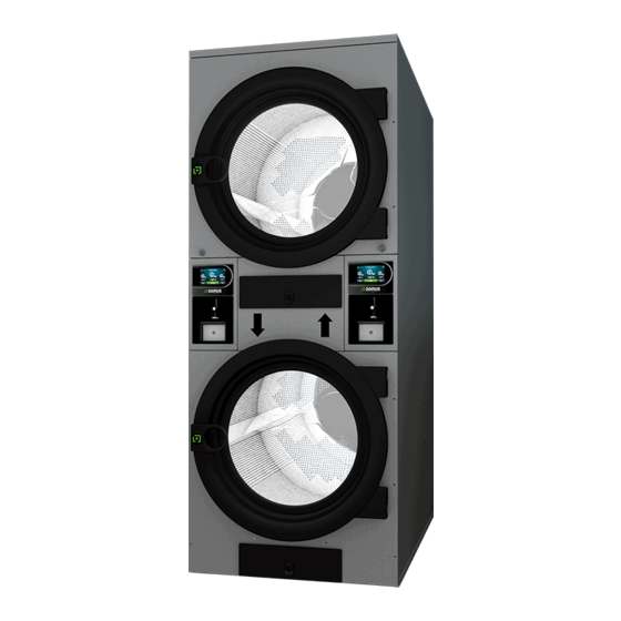
2.1. Overview and dimensions GENERAL DIMENSIONS (indicated in mm): MODEL 25 Lb 35 Lb in (mm) 78 (1980) 78 (1980) in (mm) 57 (1447) 57 (1447) in (mm) 10.2 (259) 10.2 (259) in (mm) 48.6 (1234) 48.6 (1234) in (mm) 63.8 (1620) 63.8 (1620) in (mm) -
Page 11: Installation
3. INSTALLATION Install the machine according to current regulations. The installation must conform with local codes or, in the absence of local codes, with the National Fuel Gas Code, ANSI Z223.1/NFPA 54, or the Natural Gas and Propane Installation Code, CSA B149.1 nstall the machine according to current regulations. -
Page 12: Location
- LOCATION OF BOLTS 1 AND 2 - UNSCREW USING A FLAT NO 13 SPANNER 3.2.2. Location. Install the machine in a big room to obtain efficient work conditions and to guarantee the sufficient ease of movement of the workers using the machine. The definitive position of the machine must allow its correct use. -
Page 13: Levelling
3.2.3. Levelling. - Do not anchor the machine, simply put it on a flat and levelled surface. Position the four adjustable feet supplied and found inside the machine. A good levelled base is important for correct operation. Procedure: - The machine must be supported on all four legs so that it stands firmly on the ground and does not rock. -
Page 14: Output Pipe
3.3.2. Output pipe Damp air should be channelled to the outside by connecting a pipe with a net diameter equal to the exterior diameter of the steam output pipe. The extraction air should be taken outside the premises and must never be connected to other fluepipes already in use for removing vapours from other fuels. - Page 15 Note: For installations with longer lengths of piping and/or more bends, please refer to the technical service. It may be necessary to enlarge the diameter of the piping or even to install an auxiliary vacuum in the installation. Each machine should preferably have an independent steam outlet. If this is not possible: Always make connections in Y.
-
Page 16: Electrical Connection
A table is given below listing the equivalent diameters required to connect various dryers to one common steam outlet and the minimum area of the fresh air inlet (see section 3.3.1): Number of dryers Diameter of the output pipe (in) Minimum area of 1007 1782... -
Page 17: Connection To Gas (Only Gas Models)
Electrical Connection 25 Lb / 35 Lb Voltage and Standard Wiring 120V 1N Frequency Cable section 120V 1N+G / Fuse Nº x AWG /A 3 x 12 / 15 Input terminals, electrical mains connection. 3.5. Connection to gas (only gas models) Although the appliance has two dryers which operate independently, there is only one gas inlet. - Page 18 Once the installation is completed, it is necessary to make the following DRIP TEST: Turn on the burners. With the help of a brush, apply soapy water to the gas inlet joints. Check if bubbles form. If so, disassemble the valves, clean them and reassemble them. Do not use a soap that is too corrosive.
-
Page 19: Injector Replacement / Conversion Kits
3.6. Injector replacement / Conversion kits WARNING: This conversion kit shall be installed by a qualified service agency in accordance with the manufacturer’s instructions and all applicable codes and requirements of the Authority Having Jurisdiction. If the information in these instructions is not followed exactly, a fire, explosion or production of carbon monoxide may result causing property damage, personal injury or loss of life. - Page 20 PROCEDURE: All the dryers are fitted with a 1/2in (20.95mm) “E” gas inlet. Never connect a pipe with an inner diameter less than this. 1- Locate the Injector “D” on the left side of the valve covered by a metal plate. Unscrew the injector until it comes out using the wrench no.
- Page 21 Before starting the machine after a gas conversion, a leak test must be carried out: To carry out the test, open the gas to the device with the device OFF and use a specific spray type bubble detector to propane gas or a specific leak detector for propane gas.
- Page 22 To check the ignition sequence the following steps should be followed: 1.- Load the appliance with the fabric to dry. 2.- Choose a high temperature set point, for example maximum temperature. 3.- Start the drying cycle. Once the drying cycle has started, the fan and drum motor will start immediately, and the gas heater will try to ignite after 30 seconds.
-
Page 23: Operation Of Electronic Control
4. OPERATION OF ELECTRONIC CONTROL (MODEL UDTM - UDLM) 4.1. Principle and description of the control of the machine The machine is controlled using an electronic microprocessor able to control the activation and deactivation of the different inputs and outputs of the system. Communication with the user is carried out using a keypad with keys and indicator lights (LED) which indicate the states of the machine. -
Page 24: Information Displayed With The Indicator Lights
4.2.1. Information displayed with the indicator lights The indicator lights (LED) show the machine modes, the temperature settings and the time remaining, in the following way (in the previous picture these are points 2, 4 and 6): Indicator Mode indicator Machine status Remarks Machine stopped /... -
Page 25: Functions Associated To The Buttons
• Remaining time display with machine running: Indicators Time Indicators Time Indicators Time Indicators Time 60’ 60’ 60’ 60’ 50’ 50’ 50’ 50’ 40’ 40’ 40’ 40’ 65-51’ 50-41’ 40-31’ 30-21’ 30’ 30’ 30’ 30’ 20’ 20’ 20’ 20’ 10’ 10’... -
Page 26: Self-Recognition Mode
Time Time per Time per Time per pulse Switch Switch Switch Switch pulse (s) pulse (s) pulse Position Position Position Position 010000 100000 110000 000000 mode 000001 010001 100001 110001 000010 010010 100010 110010 000011 010011 100011 110011 000100 010100 100100 110100 000101... -
Page 27: Other Functions
4.2.5. Other functions • Reset to factory parameters: The factory parameters can be reset with the following sequence: o The electrical power supply should be disconnected from the machine. o With the machine stopped, press the Start button. While the Start button is pressed, reconnect the electricity. -
Page 28: How To Finish Drying
4.3.1. How to finish drying • OPL Mode: Push START/STOP key (1) Self-service Mode: • Push START/STOP key (1) 4.4. ALARMS AND WARNINGS The open door and open filter alarms lead to the pausing of the current programme. When the conditions triggering the alarm disappear, the drying cycle can be restarted as soon as the alarm is removed. -
Page 29: Principle And Description Of The Touch Control
LED red Alarm Meaning Possible solutions flashes AL-1 Door open * Close the door. AL-2 Filter cover open * Close the filter cover. AL-3 No flame (only for * Check gas supply cock open. gas-heated versions) * Check that the pressure is correct. AL-4 Pressure drop failure * Check that the outlet conduit is free, check that it is... -
Page 30: Opl: Screen Off
6.1. OPL: SCREEN OFF 1. Machine identifier 2. Laundrette message 3. Logo 4. Time 5. Date 6. Model, heating type and software version Touch anywhere on the screen to be redirected to the ‘Main Screen’’ 6.2. OPL: MAIN SCREEN 1. Machine identifier 2. -
Page 31: Opl: Run Screen
9. Start: button to start the central programme on screen. 10. Programme cycles: press on the selected programme icon, the phases of the programme will be displayed. Press on the icons in the right-hand vertical column to modify the different parameters in each phase one by one. -
Page 32: Self-Service: Selection Screen 1 - Buttons
• See/edit settings/true values: press the setting values to edit for the current drying cycle. Outputs: the status of each of the outputs is displayed. • Inputs: the status of each of the inputs is displayed. • 6.4. SELF-SERVICE: SELECTION SCREEN 1 - BUTTONS: In the self-service machines, to run a programme it is always necessary to insert the required money first, either in coins or using alternative payment methods (card or mobile). -
Page 33: Self-Service: Selection Screen 2 - Payment
1. Machine identifier 2. Time 3. Programme name 4. Programme length 5. Maximum programme temperature 6. Price for the minimum programme time 7. Total number of programmes (max. 16) 8. Side browser arrows 9. Active button: payment may be made in this first screen. When the cost of the programme has been reached, the price disappears and the colour of the button changes to green, a tick is displayed instead of the price, indicating that the programme is ready to be run. -
Page 34: Self-Service: Run Screen
6.6. SELF-SERVICE: RUN SCREEN The self-service run screen is very similar to that of the OPL screen. It contains the following elements: 1. Machine identifier 2. Time 3. Programme name 4. Position of the programme in favourites and programme length 5. -
Page 35: Programme Management
7.1. Programme management Cycle library: all the available cycles are stored in this folder by default, but it is also possible to create new personalised cycles or edit already existing cycles. The programmable parameters in the drying cycles are as follows: 1. -
Page 36: Configure System
In dispenser cycles (emission of perfume or product for the treatment of laundry) the parameters to be determined are as follows: 1. Objective dispenser temperature (ºC/ºF) As soon as the temperature falls below this temperature, the dispensing operation will take place. 2. - Page 37 Activate/deactivate anti-crease function. At the end of the drying cycle, if the laundry is not removed from the machine, the anti-crease function activates the drum for a few seconds, alternating between on and off, to reduce the formation of creases in the fabrics. Activate/deactivate sump resistor (only dryers with heat pump).
-
Page 38: How To Run A Drying Cycle
8. HOW TO RUN A DRYING CYCLE • OPL mode: When the machine is in WAIT mode, proceed as follows: 1. If the OFF screen is displayed, touch the screen anywhere and the main menu will be displayed. 2. In the main menu, use the arrows to select the required programme and press START to activate the drying cycle. -
Page 39: How To Finish Drying
8.1. How to finish drying • OPL Mode: o Push STOP key (8) o A confirmation message will be requested. To return to the current programme, press the cross, and to confirm the detention of the programme press the tick. •... -
Page 40: Alarms And Warnings
WARNING: ELECTRICAL SHOCK HAZARD Electrical shock can result in death or serious injury. If the water dispensing system is activated do not attempt to operate the dryer. If the water dispensing system is activated have the dryer inspected by a qualified agency before operating the dryer. Machines that have a water inlet use it to lower the temperature in the drum, if certain conditions are reached, until the temperature is safe. -
Page 41: Maintenance
The different possible alarms and warnings are listed below (explained in more detail in the full manual): ALARM/ ALARM/ DESCRIPTION DESCRIPTION WARNING WARNING NTC2 probe disconnected or out of Door open range (upper drum temperature) NTC3 probe disconnected or out of Filter cover open range (temperature of air input to drum) -
Page 42: Fluff Filter
The machine operation does not require any type of maintenance. Bearing greasing is permanent for the machine's entire useful life. THE PERFORMANCE OF THE DRYER LARGELY DEPENDS ON GOOD MAINTENANCE AND CLEANING OF ALL THESE ELEMENTS. 10.1. Fluff filter The appliance includes an independent fluff filter for each dryer located at the front of the machine. These are in the upper part for the upper dryer and in the lower part for the lower dryer. -
Page 43: Air Extractor
10.3. Air extractor 10.3.1. Fan blades: Check once a year cleaning the fan blades. Blades and blocked conduits prevent the air from circulating. A periodic review of the extraction system should be carried out once every month. Verify that the exhaust duct, screen, etc. -
Page 44: Troubleshooting
11. TROUBLESHOOTING 11.1. Problem-Cause-Solution Table Problem Cause Solution Time at 0: Select a correct time. Door open Close the door. The dryer does not Filter open Close filter. start up Check the condition of fuses. No power supply Check mains voltage is correct. Normal operation of the machine. -
Page 45: Informations Relatives À La Sécurité
1. INFORMATIONS RELATIVES À LA SÉCURITÉ Veuillez lire ce guide avant d'utiliser ou d'installer le sèche-linge. • Conservez-le dans un lieu sûr pour pouvoir vous y reporter à l'avenir. • Ce guide doit accompagner la machine en cas de vente à une tierce partie. •... -
Page 46: Caractéristiques Générales
2. CARACTÉRISTIQUES GÉNÉRALES Nos différents modèles et accessoires de sèche-linge ont été conçus pour répondre aux plus hauts standards de performance, fiabilité et capacité de séchage. De série, la machine est équipée du système COOL-DOWN (refroidissement progressif) pour éviter les brûlures en vidant la charge et une éventuelle combustion spontanée. -
Page 47: Vue D'ensemble Et Dimensions
2.1. Vue d'ensemble et dimensions DIMENSIONS GÉNÉRALES (indiquées en mm) : MODEL 25 Lb 35 Lb in (mm) 78 (1980) 78 (1980) in (mm) 57 (1447) 57 (1447) in (mm) 10.2 (259) 10.2 (259) in (mm) 48.6 (1234) 48.6 (1234) in (mm) 63.8 (1620) 63.8 (1620) -
Page 48: Installation
3. INSTALLATION Installez la machine conformément aux réglementations en vigueur. L'installation doit être conforme aux codes locaux ou, en l'absence de codes locaux, au National Fuel Gas Code, ANSI Z223.1 / NFPA 54, ou au Natural Gas and Propane Installation Code, CSA B149.1 3.1. -
Page 49: Situation
- POSITION DES VIS 1 ET 2 - DÉVISSER À L'AIDE D'UNE CLÉ PLATE Nº 13 3.2.2. Situation. Placez l'appareil dans un grand local pour obtenir des conditions de travail efficaces et assurer une aisance suffisante au personnel utilisateur de la machine. La position définitive de la machine doit permettre sa correcte utilisation. -
Page 50: Mise À Niveau
3.2.3. Mise à niveau. - Ne fixez pas la machine, posez-la simplement sur une surface plane et nivelée. Placez les 4 pieds réglables fournis et se trouvant à l'intérieur de la machine. Il est important que la base soit bien nivelée pour que la machine fonctionne correctement. -
Page 51: Tuyauterie De Sortie
3.3.2. Tuyauterie de sortie L'air humide doit être canalisé à l'extérieur grâce à un raccord de tuyau, dont le diamètre net correspond au diamètre extérieur du tuyau de sortie de buées, situé dans la partie inférieure arrière de la machine. L'air évacué... - Page 52 Remarque : Pour les installations avec plus de 8 mètres linéaires de tuyauterie et / ou plus d'un coude, veuillez consulter le service technique. Il peut être nécessaire d'augmenter le diamètre du tuyau ou même de monter sur l'installation même un aspirateur auxiliaire. Il vaut mieux que chaque machine dispose de sa propre sortie de buées.
-
Page 53: Connexion Électrique
Vous trouverez ci-dessous un tableau sur lequel vous pouvez consulter le diamètre équivalent nécessaire pour relier plus sèche-linge à une sortie commune de buées, ainsi que la surface minimale d'entrée d'air frais (reportez-vous au paragraphe 3.3.1): Nombre de sèche- linge Diamètre du tuyau de sortie (po) Surface minimale... -
Page 54: Connexion À Gaz (Uniquement Les Modèles À Gaz)
Electrical Connection 25 Lb / 35 Lb Voltage and Standard Wiring 120V 1N Frequency Cable section 120V 1N+G / Fuse Nº x AWG /A 3 x 12 / 15 Bornes d'entrée, raccordement électrique. 3.5. Connexion à gaz (uniquement les modèles à gaz) L'appareil, bien que composé... - Page 55 Pour tous les types de gaz, il est nécessaire d'installer une vanne manuelle et un filtre à gaz. Pour le gaz GPL uniquement, installez un régulateur de pression. Assurez-vous que la saleté ne pénètre pas dans la vanne pendant la tuyauterie. Une fois l’installation terminée, il est nécessaire de réaliser le DRIP TEST suivant: Allumez les brûleurs.
-
Page 56: Remplacement Des Injecteurs / Kits De Conversion
3.6. Remplacement des injecteurs / Kits de conversion ATTENTION : Ce kit de conversion doit être installé par une agence de service qualifiée conformément aux instructions du fabricant et à tous les codes et exigences applicables de l'autorité compétente. Si les informations contenues dans ces instructions ne sont pas suivies exactement, un incendie, une explosion ou la production de monoxyde de carbone peut en résulter, causant des dommages... - Page 57 PROCÉDURE : Tous les sèche-linge disposent d'une entrée de gaz « E » de 1/2” (20.95mm). Ne connectez jamais de tuyau avec un diamètre intérieur inférieur à celui-ci. 1- Localisez l'injecteur “D” dans la partie gauche de la vanne, recouvert d'une plaque métallique. Dévissez l'injecteur jusqu'à...
- Page 58 Avant de démarrer la machine après une conversion de gaz, un test de fuite doit être effectué: Pour effectuer le test, ouvrir le gaz avec l'appareil éteint et utiliser un détecteur de bulles de type spray spécifique au gaz propane ou un détecteur de fuite spécifique pour le gaz propane. Tous les points et connexions à...
- Page 59 Pour vérifier la séquence d'allumage, suivre les étapes suivantes 1. Charger l'appareil avec le tissu à sécher. 2. Choisisser un point de consigne de température élevée, par exemple la température maximale. 3. Démarrer le cycle de séchage. Une fois que le cycle de séchage est en marche, le ventilateur et le moteur du tambour démarreront immédiatement et le chauffage à...
-
Page 60: Fonctionnement Du Contrôle Électronique
FONCTIONNEMENT DU CONTRÔLE ÉLECTRONIQUE (MODÉLE UDTM - UDLM) 4.1. Principe et description du contrôle de la machine La machine est contrôlée au moyen d'un microprocesseur électronique qui contrôle l'activation, et la désactivation des différentes entrées et sorties du système. La communication avec l'utilisateur s'effectue par l'intermédiaire d'un clavier contenant des boutons-poussoirs et des indicateurs lumineux (LED), qui indiquent les états de la machine. -
Page 61: Informations Visualisées À L'aide Les Indicateurs Lumineux
4.2.1. Informations visualisées à l'aide les indicateurs lumineux Les indicateurs lumineux (LED) montrent les états de la machine, la température de consigne et le temps restant, comme suit (sur la figure précédente, ce sont les points 2, 4 et 6) : Indicateur État indicateur État de la machine... -
Page 62: Fonctions Associées Aux Touches
• Visualisation du temps restant avec la machine en marche : Indicateurs Durée Indicateurs Durée Indicateurs Durée Indicateurs Durée 60’ 60’ 60’ 60’ 50’ 50’ 50’ 50’ 40’ 40’ 40’ 40’ 65-51’ 50-41’ 40-31’ 30-21’ 30’ 30’ 30’ 30’ 20’ 20’... -
Page 63: Mode Autoreconnaissance
Position Temps Position Temps Position Temps Position Temps par impulsion switch impulsion switch impulsion switch impulsion switch Mode 010000 100000 110000 000000 000001 010001 100001 110001 000010 010010 100010 110010 000011 010011 100011 110011 000100 010100 100100 110100 000101 010101 100101 110101 000110... -
Page 64: Autres Fonctionnalités
4.2.5. Autres fonctionnalités Réinitialisation des paramètres d'usine: Il est possible de réaliser une réinitialisation des • paramètres d'usine en utilisant la séquence suivante : o L'alimentation électrique de la machine devra être coupée. o Avec la machine est arrêtée, vous devrez maintenir le bouton Start enfoncé. Avec le bouton Start enfoncé, vous devrez rebrancher l'alimentation électrique. -
Page 65: Comment Terminer Le Séchage
4.3.1. Comment terminer le séchage • Mode OPL: Appuyer la touche START/STOP (1) • Mode libre service: Appuyer la touche START/STOP (1) 4.4. ALARMES ET AVERTISSEMENTS Les alarmes d'ouverture de porte et d'ouverture de filtre entraînent une pause du programme en cours. Lorsque les conditions d'alarmes disparaissent, le séchage peut recommencer dès que l'alarme est supprimée. -
Page 66: Principe Et Description Du Commande Touch
Clignotements Alarme Signification Solutions possibles rouge voyant AL-1 Porte ouverte * Fermer la porte. AL-2 Couvercle du filtre * Fermer le couvercle du filtre. ouvert AL-3 Absence de flamme * Vérifier que le robinet d'arrivée de gaz est ouvert. (uniquement * Vérifier que la pression est bonne. -
Page 67: Opl : Écran Off
Vous pouvez modifier légèrement les informations extraites à l’écran à partir du menu HUD ou d’affichage. 6.1. OPL : ÉCRAN OFF 1. Identificateur de machine 2. Message blanchisserie 3. Logo 4. Heure 5. Date 6. Modèle, type de chauffage et version de logiciel En appuyant n’importe où... -
Page 68: Opl : Écran D'exécution
7. Durée de séchage ou humidité relative finale du programme (en minutes ou % HR) : il existe deux options pour établir la fin d’un séchage, la durée totale en minutes du séchage ou l’humidité relative à atteindre. L’une exclut l’autre (l’option de contrôle de l’humidité est requise). 8. -
Page 69: Libre-Service : Écran De Sélection 1 - Boutons
12. Mettre en pause programme : une fois mis en pause, le bouton deviendra une icône pour redémarrer (play). 13. Stop (arrêter/annuler le programme) 14. Menu exécution : accès au menu d’exécution, où les paramètres pourront être affichés et modifiés en cours de séchage. •... -
Page 70: Libre-Service : Écran De Sélection 2 - Paiement
1. Identificateur de machine 2. Heure 3. Nom de programme 4. Durée de programme 5. Température maximale du programme 6. Prix pour la durée minimale du programme 7. Nombre total de programmes (max. 16) 8. Flèches latérales de navigation 9. Bouton actif : sur ce premier écran, le paiement pourra être réalisé. En parvenant au montant d’un programme, le prix disparaîtra, le bouton deviendra vert et un tick sera affiché... -
Page 71: Libre-Service : Écran D'exécution
6.6. LIBRE-SERVICE : ÉCRAN D'EXÉCUTION L’écran d’exécution en libre-service ressemble énormément à celui du mode OPL. Il comporte les éléments suivants : 1. Identificateur de machine 2. Heure 3. Nom de programme 4. Position du programme dans favoris et durée du programme 5. -
Page 72: Gestion De Programmes
7.1. Gestion de programmes Bibliothèque de phases : dans ce dossier, toutes les phases disponibles sont stockées par défaut, mais vous pourrez également en créer de nouvelles personnalisées ou éditer celles existantes. Les paramètres pouvant être programmés sont les suivants dans les phases de séchage : 1. -
Page 73: Configurer Le Système
Dans les phases de dosage (émission de parfum ou de substance pour le traitement du linge), les paramètres à déterminer sont : 1. Température ciblée de dosage (ºC / ºF). Le dosage sera exécuté lorsque cette température est atteinte. 2. Temps de dosage (secondes) : durée pendant laquelle la machine libère le parfum. 3. - Page 74 Activer/désactiver intelligent dry (séchage intelligent, adaptation de la vitesse, kit de contrôle de l’humidité requis) Activer/désactiver la fonctionnalité antiplis. À la fin du cycle de séchage, si le linge n’est pas extrait de la machine, le programme antiplis active le tambour pendant quelques secondes en alternance pour réduire le froissement du tissu.
-
Page 75: Comment Réaliser Un Séchage
8. COMMENT RÉALISER UN SÉCHAGE • Mode OPL: Lorsque la machine est EN VEILLE, procédez comme suit : 1. Si l’écran OFF est affiché, appuyer n’importe où sur l’écran, l’écran principal sera affiché. 2. Sur l’écran principal, sélectionner le programme souhaité... -
Page 76: Comment Terminer Le Séchage
8.1. Comment terminer le séchage • Mode OPL: o Appuyer la touche STOP(8) o Un message de confirmation vous sera demandé. Pour revenir au programme en cours, appuyez sur la croix et pour confirmer la suppression du programme, appuyez sur la coche. •... -
Page 77: Alarmes Et Avertissements
AVERTISSEMENT: RISQUE DE CHOC ÉLECTRIQUE Un choc électrique peut entraîner la mort ou des blessures graves. Si le système de distribution d'eau est activé, n'essayez pas de faire fonctionner le sèche-linge. Si le système de distribution d'eau est activé, faites inspecter le sèche-linge par une agence qualifiée avant d'utiliser le sèche-linge. -
Page 78: Entretien
Les différentes alarmes et avertissements possibles sont ceux spécifiés ci-dessous (expliqués de façon plus détaillée dans le mode d’emploi complet) : ALARME / ALARME / AVERTIS- DESCRIPTION AVERTIS- DESCRIPTION SEMENT SEMENT Sonde NTC2 déconnectée ou hors plage Porte ouverte (température supérieure tambour) Sonde NTC3 déconnectée ou hors plage Couvercle du filtre ouvert (température entrée air au tambour) -
Page 79: Filtre À Bourre
LE RENDEMENT DU SÈCHE-LINGE DÉPEND EN BONNE MESURE DU BON ENTRETIEN (NETTOYAGE) DE CES ÉLÉMENTS. 10.1. Filtre à bourre L'appareil comprend un filtre à bourre indépendant pour chaque sèche-linge, situé dans la partie avant de l'appareil. Ils se trouvent dans la partie haut pour le sèche-linge d'en haut et dans la partie inférieure pour le sèche-linge d'en bas. -
Page 80: Extracteur D'air
10.3. Extracteur d'air 10.3.1. Pales de la turbine: Vérifiez une fois par an le nettoyage des pales de ventilateur Les lames et conduits obstrués empêchent la circulation d'air. Un examen périodique du système d'extraction doit être effectué une fois par mois. Vérifiez que le conduit d'évacuation, l’écran , etc. -
Page 81: Problèmes Et Solutions
11. PROBLÈMES ET SOLUTIONS 11.1. Tableau de Problème-Cause-Solution Problème Cause Solution Temps à 0 Sélectionner un temps correct. Porte ouverte Fermer la porte. Filtre ouvert Fermer filtre. Le sèche-linge ne Vérifier que les fusibles sont en bon démarre pas état. Sans alimentation électrique Vérifier que la tension du réseau est bonne.
Need help?
Do you have a question about the UDTT-2-25 and is the answer not in the manual?
Questions and answers