
Related Manuals for THEIS VISION 2N AUTOSLOPE


Summary of Contents for THEIS VISION 2N AUTOSLOPE
- Page 1 VISION AUTOSLOPE Gebrauchsanleitung Instruction manual Instructions de service...
-
Page 2: Table Of Contents
Inhaltsverzeichnis Vorwort....................3 Tastaturbelegung / Display ............4 Horizontalbetrieb ................5 Vertikalbetrieb / Modus Fluchten ..........5 Rotationsgeschwindigkeit ............6 Neigung ..................6 Neigung im Horizontalbetrieb ..........6 Neigung im manuellen Modus .........8 Ausblend – Modus ...............9 Scan-Modus .................9 Einstellung des Nachregelbereichs im Nivellier - und Neigungsmodus (Windy) ............10 TILT-Funktion ................10 Stromversorgung ...............11 Funk-Fernbedienung FB-V (Option) ..........12... -
Page 3: Vorwort
Vorwort VISION AUTOSLOPE ...für den Profi am Bau. Der Rotationslaser THEIS VISION 2N AUTOSLOPE setzt Maß- stäbe im Bereich der vollautomatischen Profilaser. Er ist das Ergebnis langjähriger Erfahrung und innovativer Technik. Der qualitativ hochwertige Baulaser zeichnet sich durch Robustheit sowie höchster Präzision aus - Made in Germany - und sollte auf keiner Baustelle fehlen. -
Page 4: Tastaturbelegung / Display
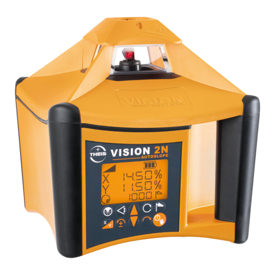
Tastaturbelegung / Display Zielfernrohr (Option) Optisches Visier Laseraustritt - Rotation Akkufach Produktinfos (Rückseite) Via QR-Code u.a. Ladebuchse Gebrauchsanleitung Neigung Nivellier- Endanschlag , Batterie- Manueller anzeige Lageänderung anzeige Modus X /Y- Achs - Neigung Windy Scan Drehzahl oder Ausblenden Scan beenden Störung Neigung Linksdrehung... -
Page 5: Horizontalbetrieb
Horizontalbetrieb Stativ ausrichten und VISION mit Stativschraube fest anziehen. Die Ausrichtgenauigkeit beeinflusst die Größe des Neigungsbereichs. Mit Ein/Aus-Taste das Gerät einschalten. Es blinkt die Nivellieranzeige im beleuchteten Dis- play. Falls der Stativkopf stärker als 5° geneigt ist, wird dies nach kurzer Zeit durch schnelles Blinken des Laserstrahls und des Alarm-Symbols angezeigt. -
Page 6: Rotationsgeschwindigkeit
Rotationsgeschwindigkeit Die Rotationsgeschwindigkeit lässt sich in 5 Stufen regulieren: 0, 200, 600, 800 und 1000 U/min. Nach dreimaligem Drücken der Rotationstaste hält der Laser an (Drehzahl 0). Durch weiteres Drücken der Taste wird die Rotationsgeschwindigkeit jeweils er- höht. Im Stillstand kann der Laserpunkt mit den Tasten Links-/Rechtsdrehung bewegt werden. - Page 7 Durch gleichzeitiges Drücken der Pfeiltasten wird die Anzeige auf 0 gesetzt. 3-ter Tastendruck: Y, Neigungsanzeige und 1. Ziffer Neigungswert blinken im Display. Neigung der Y-Achse kann jetzt sinngemäß wie bei der X-Achse eingestellt werden. 4-ter Tastendruck: Bestätigung der Eingabe Danach beginnt zunächst eine erneute Nivellierung, angezeigt durch die blinkende Nivellieranzeige im Display.
-
Page 8: Neigung Im Manuellen Modus
Neigung im manuellen Modus Um beispielsweise größere Neigungen unter zu Hil- fenahme eines Winkeltisches einstellen zu können, oder um bauseits vorgegebene Neigungen aufzu- nehmen, muss die Automatik des Gerätes ausge- schaltet werden. Dies geschieht durch langen Tastendruck der Ein- /Aus-Taste (ca. 5 Sek). Hinweis im Display durch blinkende Hand. -
Page 9: Ausblend - Modus
Ausblend – Modus Im Ausblendmodus kann der Laseraustritt auf eine bestimmte Größe und Position gebracht werden. Dies ist nur bei rotierendem Laserstrahl möglich. Durch 1x Drücken wird die kleinste Ausblendmög- lichkeit aktiviert, durch weiteres Drücken vergrößert sich der Ausblendbereich. Mit dem 4 - ten Tasten- druck wird der Ausblendmodus wieder verlassen. -
Page 10: Einstellung Des Nachregelbereichs Im Nivellier - Und Neigungsmodus (Windy)
Einstellung des Nachregelbereichs im Nivellier - und Neigungsmodus (Windy) Falls während der Arbeit durch Wind, Bodenschwin- gungen oder leichte Stöße die Rotation immer wie- der unterbrochen wird, weil das Gerät nachregeln muss, besteht die Möglichkeit, über die Windy- Funktion hier Abhilfe zu schaffen. Durch Drücken der Windy –... -
Page 11: Stromversorgung
Wenn der Akku voll ist, werden alle Bal- ken angezeigt. Nachladen des Akkus bei Raumtemperatur nur mit THEIS Standard-Netzgerät über die Ladebuchse un- terhalb des Lasers. Das Laden unter +5°C kann zu einem Defekt der Akkus führen. Ein Nachladen ist auch während des Betriebs mög- lich. -
Page 12: Funk-Fernbedienung Fb-V (Option)
Funk-Fernbedienung FB-V (Option) Die Funk-Fernbedienung ist bidirektional konzipiert. Alle Informatio- nen die im Display des Lasers angezeigt werden, finden sich auch im beleuchteten Display der Fernbedienung wieder. Die Tastensym- bole auf dem Bedienfeld, entsprechen den Tasten auf der Lasertas- tatur. Die Betriebsart MANUELL fehlt, um eine versehentliche Eingabe dieser Funktion zu unterbinden. - Page 13 der Standby-Modus beendet werden und das Gerät kehrt in den Normalbetrieb zurück, wie nach dem erneuten Einschalten des Ge- rätes. Die maximale Standby-Zeit lässt sich im Info-Menü einstellen (siehe Kapitel 14). Wird die Standby-Zeit überschritten schaltet sich der Laser aus. Die Stromversorgung erfolgt über zwei Alkaline Mikro AAA Batte- rien.
-
Page 14: Empfänger Te 90
Empfänger TE 90 Tastaturbelegung Numerische - / Textanzeige Pfeil für Bewegungsrichtung Zentrum Balken Batterieanzeige Pfeil für Bewegungsrichtung Anzeigegenauigkeit Anzeige akustisches Signal Magnet LED Richtungsanzeige Display (auch Rückseite) Sensorfenster LED Zentrum Kerbe Zentrum LED Richtungsanzeige Taste: LEDs Ein/Aus Röhrenlibelle Menü: Pfeiltaste oben Taste An / Aus Taste: Taste akustisches Signal /... -
Page 15: Standardbetrieb
Standardbetrieb Ein- und Ausschalten des Gerätes Drücken Sie die Taste An / Aus Anpassen der Lautstärke Durch langes Drücken der Taste akustisches Signal kann die Laut- stärke angepasst werden: Leise / Laut / Aus ➢ Laut: Lautsprecher-Symbol wird dauerhaft angezeigt; Anzeige “Hi”... - Page 16 Benutzerdefinierte Sollhöhe Sie können, innerhalb von -10 und +40 mm um die Zentrumskerbe, eine beliebige Sollhöhe (Nullpunkt festlegen). Dazu halten Sie wäh- rend des Laserempfangs die Taste Anzeigegenauigkeit für zwei Se- kunden gedrückt. Bei Erfolg hören Sie einen Bestätigungston und ein asymmetrisches Pfeil-Symbol erscheint im Display.
-
Page 17: Stromversorgung - Empfänger
• Unt - Maßeinheit: mm / cm / Zoll (in) / Zoll in Brüchen (f.in) Standard: mm. Wählen Sie die gewünschte Maßeinheit aus. • o.o.b - Verlust des Laserstrahls: An (On) / Aus (OFF) Standard: Aus. Schaltet die Anzeige für den Verlust des Laserstrahls an und aus. -
Page 18: Überprüfung Der Justierung
Überprüfung der Justierung Laser-Nivellier, wie unter Punkt 2 beschrieben (aber auf einem sehr gut ausgerichteten Stativ) aufbauen und entlang einer etwa 30 m lan- gen Messstrecke – beispielsweise mit der X-Achse beginnend – aus- richten und einschalten. Am Ende der Messtrecke in Höhe des Laserstrahls eine Markierung vornehmen. - Page 19 US wählen (Achtung: Nur für USA und AUS) Speichern und nächster Menüpunkt % / ‰ - Einstellung Einstellung (% - Einstellung ist Standard) Speichern und nächster Menüpunkt Startdrehzahl wählen 600, 800 oder 1000 U/min einstellen Speichern und nächster Menüpunkt Lcdb Display Beleuchtungsdauer SEC.
- Page 20 Info und Einstellungen FB – V Zusammen drücken Seriennummer z.B. 144522 Nächster Menüpunkt Software Version z.B. build 089 Nächster Menüpunkt Automatische Kanalwahl oder manuell einstellen z.B. CH5 EU Kanal wählen 1 - 16 mit bestätigen. Kanal CH Auto: Voreinstellung für automatische Wahl) US wählen (Achtung: Nur für USA und AUS) Speichern und nächster Menüpunkt...
-
Page 21: Lieferumfang
Keine Garantieansprüche bestehen auf kostenlose Behebung von Fehlern, die durch unsachgemäße Behandlung oder Aufbewahrung entstanden sind sowie jegliche Schadensersatzansprüche, insbe- sondere auch solche auf mittelbare Schäden. Ferner erlischt jeder Garantieanspruch, wenn technische Eingriffe von fremder Seite – also nicht durch die Firma THEIS – vorgenommen werden. -
Page 22: Kurzanleitung
Kurzanleitung Ein-/Ausschalten Manueller Modus (5 Sek. drücken) Drehzahl (U/min) 5 Stufen: 0 - 1000 Verfahren des Laserstrahls (Schrittbetrieb) Neigung Anzeige letzte Eingabe Eingabe X Eingabe Y Bestätigung Ziffern - und Vorzeichenwahl Ausblendmodus Aktivierung 90 bis 270°: Deaktivierung Positionieren des Ausblendbereichs Scanmodus 5 Stufen, 10 bis 80°... -
Page 23: Technische Daten
Technische Daten Laser Laserklasse / High Power 2 / 3R Wellenlänge 635 - 660nm Ausgangsleistung / High Power < 1mW / < 5mW Reichweiten Siehe Empfänger Selbstnivellierbereich ± 5° Nivelliergenauigkeit ± 1,5 mm / 30 m 3,4,6 Neigungsgenauigkeit 0,025 % bis 5% Neigung Neigungs –... -
Page 24: Lieferantenerklärung / Sicherheitshinweise
Inneren des Gerätes. Service darf nur von autorisierten Stellen ausgeführt werden. Sicherheitsvorschriften für THEIS HIGH-POWER LASERGERÄTE Klasse 3R Der Anwender muss die BGVB2 (Unfallverhütungsvorschrift für La- serstrahlung in Deutschland beachten. • Dieses Produkt darf nur von geschultem Personal bedient wer- den, um die Bestrahlung durch gefährliches Laserlicht zu ver-... -
Page 25: Entsorgung
(WEEE - Reg.-Nr. DE 10598800) Gemäß der Richtlinie 2006/66/EU müssen nicht mehr gebrauchsfä- hige THEIS Lasergeräte oder verbrauchte Akkus/Batterien recycelt werden oder können direkt abgegeben werden bei Theis Fein- werktechnik. Akkus/Batterien: Batterien und Akkus sind Sondermüll und dürfen nicht in den Haus- müll, ins Feuer oder Wasser gelangen. - Page 26 Contents Keyboard /Display ..............28 Horizontal Operation ..............29 Vertical Operation/Alignment Mode ...........29 Rotation speed ................30 Slope ..................30 Slope in Horizontal operation ........30 Slope in Manual Mode ...........32 Mask Mode ................33 Scanning Mode ................33 Setting of re-adjustment in levelling-and grade mode (Windy) ..34 TILT Function ................34 Power Supply of Laser ...............35 Radio Remote Control FB-V (Option) ........36...
- Page 27 Introduction VISION AUTOSLOPE ... for the construction professional. The rotation laser THEIS VISION 2N AUTOSLOPE sets new stand- ards in the area of fully automated professional lasers. It is the result of many years of experience and innovative technol- ogy.
-
Page 28: Keyboard /Display
Keyboard /Display Sighting telescope Optical sight (Option) Laser exit rotation Productinformation Battery compartment Via QR-Code on re- verse, e.g. Instruction Charging socket manual Slope Levelling End stop, Battery Manual display Position change display mode X/Y axis slope Windy Scan Mask Disturbance Speed or mode Scan-stop... -
Page 29: Horizontal Operation
Horizontal Operation Align the tripod and screw the VISION tight using the tripod screw. The precision of alignment affects the size of the slope range. Use the On/Off switch to switch on the device. The levelling indicator flashes on the lit display. If the tripod head is sloping by more than 5°, this is indicated by the laser beam flashing quickly and the alarm symbol being displayed. -
Page 30: Rotation Speed
Rotation speed The rotation speed can be regulated in four stages: 0, 200, 600, 800 and 1000 RPM. Pressing the rota- tion key three times the laser stops (0 RPM). Each time you press the key again, the rotation speed in- creases. - Page 31 3rd key press: Y flashes on the display. You can now use the arrow keys to set the slope of the Y axis in the same way as for the X axis. 4th key press: Confirms your input After this, the device first starts levelling again, which is shown by the flashing levelling display.
-
Page 32: Slope In Manual Mode
Slope in Manual Mode To be able to set higher grades using a level table or to record building-side specified grades, for ex- ample, you must switch off the device's automatic system. You do this by pressing the On/Off key for a long time (approx. -
Page 33: Mask Mode
Mask Mode In mask mode, you can limit the laser exit to a settable range. This is only possible with a rotating laser beam, i.e. not in scanning mode. By pressing the key three times you enlarge the masked area up from 90 to 270°. With the 4 press you leave the mask mode. -
Page 34: Setting Of Re-Adjustment In Levelling-And Grade Mode (Windy)
Setting of re-adjustment in levelling-and grade mode (Windy) To continue working due to wind, vibrations or slight shocks you can remedy this situation using the Windy function in levelling- and grade mode to ex- tend the re-adjustment range. A permanent interrup- tion of rotation will be disabled with that. -
Page 35: Power Supply Of Laser
When the battery is fully charged, all the bars are shown. Charge the battery at room temperature using only the THEIS standard mains unit connected to the charger socket below the laser. Charging at temperatures below +5°C can lead to defects in the battery. -
Page 36: Radio Remote Control Fb-V (Option)
Radio Remote Control FB-V (Option) The wireless remote control is designed on a bidirectional basis. All the information that is shown on the laser's display can also be seen on the lit-up display of the remote control. The key symbols on the operator panel correspond to the keys on the laser keypad. - Page 37 button on the remote control the standby-mode can be stopped. The instrument will return to normal operation, as if the instrument will be switched on. The maximum standby-period can be set at the info-menu (see capital 14). The laser switches off if standby-period is exceeded.
-
Page 38: Detector Te90
Detector TE90 Keyboard Numeric digits / text display Arrow for direction of movement Device symbol: Laser connected Centre bar Battery display Arrow for direction of movement Accuracy Display of audible signal Magnet LED: Direction of movement Display Sensor window (on reverse too) LED for Centre Centre notch LED: Direction of movement... -
Page 39: Operation
Operation Switching the device on / off Press the On / Off button Adjusting the volume Pressing the audible signal button cycles Low / High / Off ➢ High: Display of audible signal permanently displayed; text "Hi" for one second ➢... - Page 40 User defined on-grade level: An arbitrary level within -10 and +40mm around the Centre notch can be used as on-grade level. The user defined on-grade level is set by pressing the accuracy button for two seconds while the device is in the laser beam.
-
Page 41: Power Supply Of Detector
Default: OFF. Switch Out-of-beam display on and off. A sequence of arrows indicates if the detectorhas moved beyond the vertical recep- tion range and will indicate in which direction to move to get back to the laser beam. • Inf - Device Information Find Information about Firmware Version (Fw), Device Code (dc) and Serial Number (Sn) here. -
Page 42: Calibration Check
Calibration Check Set up the laser leveller as described in point 2 (but on an extremely well aligned tripod) and align it along a traverse length of approximately 30 metres – starting with the X axis, for example – and switch it on. - Page 43 % / ‰ - setting % setting (% setting is default) ‰ - setting Save and next menu item Select start rotation speed Select 600, 800 or 1000 rpm Save and next menu item Lcdb Display of lighting timeout SEC. 20 Select 0 –...
- Page 44 Information and settings FB – V Press buttons 144522 Serialnumber e.g. Next menu item Program Version build 089 Next menu item CH5 EU Automatic channel selection or select manual. e.g. Select channel 1 - 16 and confirm (Channel CH Auto is for automatic selection.) Select US (Attention: Only for USA und AUS) Save and next menu item 2.52...
-
Page 45: Delivery Contents
1 year) from the date of sale (date of invoice). You must return the device or its affected components for repair or replacement to THEIS immediately free of charge after you establish the defect. No guarantee claim or claim free elimination of faults due to incorrect handling or storage can be accepted;... -
Page 46: Brief Instructions
Brief Instructions Switch on/off Manual mode (press for 5 sec.) Speed On/ Off 5 steps: 0 - 1000 Traversing the laser beam (step mode) Slope Display of last input Input X Input Y Confirmation Change sign and digits Mask mode Activation of 90 to 270°: Deactivation Positioning the mask area Scanning mode... -
Page 47: Technical Data
Technical Data Laser Laser Class / High Power 2 / 3R Wavelength 635 -660nm Output Power / High Power < 1mW / < 5mW Range See detector Self-levelling range ± 5° Levelling precision ± 1,5 mm / 30 m 3,4,6 Grade accuracy 0,025 % to 5% Grade Slope –... -
Page 48: Supplier Declaration/Safety Information
There are no parts to maintain or adjust inside the device. Servicing may only be carried out by authorized persons. Safety regulations for THEIS Class 3R HIGH-POWER LASER DEVICES Users must observe BGVB2 (Accident Prevention Regulations for Laser Radiation in Germany). - Page 49 Note: This equipment has been tested and found to comply with the limits for a Class B digital device, pursuant to part 15 of the FCC Rules. These limits are designed to provide reasonable protection against harmful interference in a residential installation. This equipment generates, uses and can radiate radio frequency energy and, if not installed and used in accordance with the instructions, may cause harmful interference to radio communications.
-
Page 50: Disposal
EU countries only: In accordance with Directive 2006/66EC, non-serviceable THEIS la- ser devices or spent rechargeable batteries must be recycled or can be returned directly to:... - Page 52 Table des matières Affectation des touches / Ecran ..........53 Fonctionnement horizontal ............55 Fonctionnement vertical / Mode d'alignement......55 Vitesse de rotation ..............56 Inclinaison ..................56 Inclinaison fonctionnement horizontal ......56 Inclinaison en mode de fonctionnement manuel ..58 Mode « Masquage » ..............59 Mode « Scan » ................59 Réglage de la plage d`ajustage en mode nivellement ou en mode pente (touche Windy) ............60 Fonction TILT ................60...
-
Page 53: Affectation Des Touches / Ecran
Avant-propos VISION AUTOSLOPE ... pour les professionnels de la construction. Le laser rotatif THEIS VISION 2N AUTOSLOPE fixe une nouvelle référence dans le domaine des lasers de profil pleinement automa- tisés. Il résulte d'une longue expérience et de techniques novatrices. - Page 54 Lunette de visée (en op- Viseur optique tion) Sortie du rayon laser - Rotation Compartiment de l'accu Informations produit à l‘arrière via QR-Code, par Prise de ex. instructions de service chargement Butée finale, Affichage Statut de la Mode Inclinaison modification de du niveau batterie manuel...
-
Page 55: Fonctionnement Horizontal
Fonctionnement horizontal Aligner le trépied et fixer le VISION au moyen de la vis du trépied. La précision d'alignement influence la grandeur de la plage d'inclinaison. Démarrer l'appareil au moyen de la touche Marche/Arrêt. L'affichage du niveau clignote dans l'écran éclairé. Une inclinaison de la tête du trépied supérieure à... -
Page 56: Vitesse De Rotation
Vitesse de rotation La vitesse de rotation peut être réglée sur niveaux : 0, 200, 600, 800 et 1000 tr/min. fois sur Appuyer trois la touche « Rotation » pour arrêter le laser (vitesse 0). Appuyer à nouveau sur la touche pour augmenter la vitesse de rotation. - Page 57 3ème pression sur la touche : Y, valeur d'inclinaison et 1 chiffre de la valeur d'inclinaison clignotent à l'écran. 4ème pression sur la touche: confirmation des valeurs Une nouvelle mise à niveau commence alors, signalisée par l'affichage d'un niveau clignotant à l'écran.
-
Page 58: Inclinaison En Mode De Fonctionnement Manuel
Inclinaison en mode de fonctionnement manuel Pour, par exemple, pouvoir réglée des plus grandes inclinaisons au moyen d’une table rectangulaire, le système automatique de l’appareil doit être désactivé. Ceci se fait en maintenant la touche Marche/Arrêt enfoncée (env. 5 sec.). Le mode « Manuel » apparaît à l’écran. -
Page 59: Mode " Masquage
Mode « Masquage » En mode de masquage, la sortie du rayon laser peut être limitée dans une zone réglable. Ceci est uniquement possible lorsque le rayon laser tourne, et donc pas en mode « Scan ». Un seul appui active le plus petit masquage pos- sible (90°), chaque appui supplémentaire augmente la zone de masquage jusqu'à... -
Page 60: Réglage De La Plage D`ajustage En Mode Nivellement Ou En Mode Pente (Touche Windy)
Réglage de la plage d`ajustage en mode nivel- lement ou en mode pente (touche Windy) Pour pouvoir travailler par vent fort ou en présence de faibles chocs ou de faibles vibrations conti- nuelles du sol, il est possible d`augmenter la plage d´ajustage en mode nivellement ou en mode de pente, en activant la touche Windy. -
Page 61: Alimentation En Courant - Laser
Ne procéder au chargement de l'accumulateur à température ambiante qu'au moyen du chargeur standard THEIS raccordé à la prise de chargement placée sous le laser. Un chargement sous +5°C peut entraîner des dommages à l’accu. Il est également possible de procéder au chargement pendant le fonctionnement. -
Page 62: Télécommande Radio Fb-V (Option)
Télécommande radio FB-V (option) La télécommande radio est conçue de manière bidirectionnelle. Toutes les informations s'affichant à l'écran du laser apparaissent également sur l'écran éclairé de la télécommande. Les symboles des touches sur le champ de commande correspondent aux touches sur le clavier du laser. - Page 63 reprend son fonctionnement normal, comme après sa remise sous tension. La durée maximum de veille peut être réglée dans le menu info (voir chapitre 14). Si le temps d'attente est dépassé, le laser s'éteint. L'alimentation en courant se fait au moyen de deux piles alcalines Micro AAA.
-
Page 64: Récepteur Te 90
Récepteur TE 90 Affectation des touches Affichage numérique / textuel Flèche pour le sens de déplacement Symbole de l'appareil : raccordé au laser Barre centrale Indicateur « Batterie » Flèche pour le sens de déplacement Précision de l'affichage Indicateur « Signal acoustique » Aimant Écran Affichage de direction à... -
Page 65: Fonctionnement Standard
Fonctionnement standard Marche / Arrêt de l'appareil Appuyer sur la touche Marche / Arrêt Adaptation du volume Une pression longue sur la touche du signal sonore permet d'adapter le volume : Faible / Fort / Muet ➢ Fort : le symbole du haut-parleur reste affiché en permanence ; affichage «... - Page 66 Activation / Désactivation des LED Appuyer sur la touche « Affichage LED » pour modifier l'affichage LED. Lorsque cette option est activée, les valeurs de mesure sont affichées au moyen de LED en plus de l'affichage à l'écran. Hauteur de consigne définie par l'utilisateur Une hauteur de consigne au choix (point zéro) peut être définie entre -10 et +40 mm autour de l'encoche centrale.
-
Page 67: Alimentation En Courant - Récepteur
• AvG - Moyenne : Élevée (Hi) / Faible (Low) Par défaut : faible. Définir le réglage sur « Élevée » lorsque des va- leurs plus stables sont requises dans des conditions atmosphériques difficiles. • Unt - Unité de mesure : mm / cm / pouce (in) / pouce en frac- tions (f.in) Par défaut : mm. -
Page 68: Vérification De L'ajustage
Vérification de l’ajustage Installer le niveau laser comme décrit au point 2 (mais sur un trépied très bien aligné), l'ajuster sur une distance de mesure d'environ 30 m – par exemple en commençant par l'axe X – et l'allumer. Effectuer un marquage à la fin de cette distance de mesure, à la hauteur du rayon laser. - Page 69 Réglage % / ‰ Réglage % (le réglage % est le réglage par défaut) ‰ – Réglage Enregistrer et point suivant du menu Sélectionner le départ de régime Sélectionner 600, 800 ou 1000 tr/min Enregistrer et point suivant du menu Lcdb Durée d'éclairage de l'écran SEC.
- Page 70 Information et réglages FB- V Enfoncer les touches Numéro de fabrication 144522 par ex. Point suivant du menu Version de programme build 089 par ex. Point suivant du menu Sélection automatique du canal ou réglage manuel CH5 EU par ex. Choix du canal: 1 –...
-
Page 71: Contenu De La Livraison
Il en va de même pour toute demande de dommages et intérêts, et plus particulièrement pour les dommages indirects. Toute intervention technique de tiers – c'est-à- dire de toute personne extérieure à la société THEIS – entraîne en outre l'extinction de la garantie. -
Page 72: Instructions Succinctes
Instructions succinctes Allumer / Arrêter Mode manuel (appuyer pendant 5 sec.) Régime (tr/min.) 5 niveaux : 0 - 1000 Déplacement du rayon laser (régime pas-à-pas) Inclinaison Affichage de la dernière valeur Valeur X Valeur Y Confirmation Sélection de chiffres et de signes Mode <... -
Page 73: Caractéristiques Techniques
Caractéristiques techniques Laser Classe de laser / High Power 2 / 3R Longueur d’onde 635 - 660nm Puissance de sortie / High < 1mW / < 5mW Power Portées Cf. récepteur Plage de nivelage autom. ± 5° Précision du niveau ±... -
Page 74: Déclaration Du Fournisseur / Consignes De Sécurité
Seuls les services habilités compétents sont autorisés à pratiquer les opérations de maintenance. Prescriptions de sécurité pour les appareils laser HIGH POWER THEIS de la classe 3R L’utilisateur est tenu de respecter la BGVB2 (directive de prévention des accidents relative au rayonnement laser en Allemagne). -
Page 75: Elimination
à la directive 2006/66/EU ou éliminés dans le respect de l'environnement. Uniquement pour les pays de l’Union Européenne : Les appareils laser THEIS inutilisables ou accus usagés doivent être recyclés conformément à la directive 2006/66/EU ou peuvent être directement renvoyés à:... - Page 76 Signal de danger « Laser » pour VISION Laserwarnschild für VISION High Power Laser warning label for VISION High Power Signal de danger « Laser » pour VISION High Power Änderungen vorbehalten Subject to changes Sous réserves de modifications THEIS FEINWERKTECHNIK GMBH 35236 Breidenbach-Wolzhausen· Germany...
Need help?
Do you have a question about the VISION 2N AUTOSLOPE and is the answer not in the manual?
Questions and answers