Table of Contents
Advertisement
Quick Links
Operating Instructions
TKL-7
Congratulations on your new Theis Laser
This operating instructions contain enclosed in addition to
information on how to use the laser important safety
information.
Please note:
First read the safety instructions on the
supplement page
1 - 3
and then the operating
instructions carefully before using the laser.
Date 03/2017
4 - 15
Subject to change
1. Description
The pipe laser emits an automatically levelled or defined inclined laser beam as
reference axis. It was specially designed for pipe laying, but can also be used for a
variety of other purposes.
2. Pipe Laying made easy
Mount device over the point of reference in such a way that the banking arrows are
no longer seen (see 8.). Adjust the inclination and align the laser beam to the point
of aim. After that join pipe after pipe and align each end to the target.
3. Set-up
The laser can be set up centrically or at a constant distance above the pipe
invert. Suitable legs, tripods and fastening systems are available for this.
Note: If the diameter indicated on the feet does not correspond with the pipe
diameter, the target has to be set up directly in front of the laser and must
be adjusted to the correct height ignoring the diameter marking.
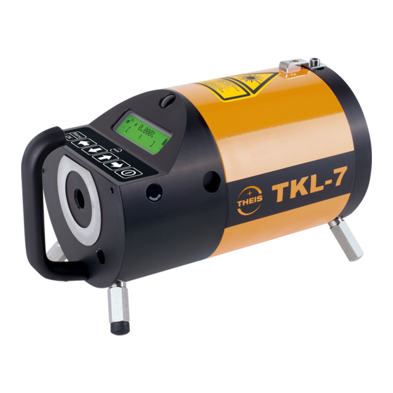
4. Laser Description
4.1 Infrared Receiver
For short distance from the back.
4.2 Keyboard
Clear layout. Big, user-friendly,
self-explanatory keys.
4.3 Charging Socket
Behind the dust guard cap.
4.4 Central Fastening Thread 5/8"
#
Bulging ground area, niro St.
4.5 Handle
For easy handling, safe transport and simple set-up.
4.6 LCD-Display
Clearly legible, illuminated display for on/off, company data, device data,
rotor speed, duty type and battery level.
Lock symbol open / closed
Algebraic sign
Inclination value
Percent sign
Status symbols:
Initialising
Adjusting inclination
Inclination adjustment finished
Power saving mode
T Kick guard active
T Blinks after jerky movement,
laser beam off
IR remote control active
Power supply
indicator
< 1/4 < 1/2 < 3/4 >3/4
Banking compensation arrow
Direction limitation
Centring indicator
Direction arrow
Centre indicator
Laser beam symbol
Laser beam off by IR remote control
5 - 13
4.7 Infrared Receiver
For a large range from the front.
4.8 Laser Warning Sign
TKL-7: Laser class 2,
P < 1 mW
TKL-7 High Power: Laser class 3R,
P < 5 mW
4.9 Robust Light Metal Housing
Plastic-coated, swept and filled with
nitrogen, 100 % watertight.
4.10 Sliding Leg (front)
For comfortable mounting in the pipe.
4.11 Identification
4.12 Battery Box
Watertight with Li Ion rechargeable battery and
safety valve.
4.13 Fixing Leg (back)
For safe mounting in the pipe.
5.
Buttons
= ON/OFF Button
The device is switched on by pressing this button.
The device and company data are then shown, followed by the operating display
with the last settings without button lock. The device is then levelled and
referenced on the zero point automatically. After the levelling phase the laser
beam and laser beam symbol stop blinking. If this does not happen, the device
must be moved into the levelling range by tilting it forwards. The display
illumination switches off after approx. 30 seconds automatically. The illumination
is switched on again by pressing the ON/OFF button shortly.To switch off the
device, press the ON/OFF button until "Auf Wiedersehen !" appears.
= Inclination Setting
or
Pressing the arrow buttons changes the inclination value by 0.001 %.
The value is changed with increasing speed if the button is kept pressed.
+
= Setting Inclination on Zero
The inclination value is set on 0.000 % by pressing the two arrow buttons at the
same time.
6 - 13
= Direction Setting
or
After setting one of the two arrow buttons the laser beam symbol changes to an
arrow. It indicates the direction of movement and the current position. When end
position is reached, the laser beam and limitation symbol begin to blink. The
setting must then be moved back within 2.5 minutes. If this is not done, the laser is
switched off automatically.
+
= Direction Centering
After pressing the two arrow buttons the device is automatically centred in
middle position.
Quick Setting
In addition to the respective arrow buttons also press the ON/OFF button.
= Button Lock
Press the button
2 x: Lock symbol select and confirm. The buttons are protected
,
against accidential adjustment. Press the Menu button 2 x again, the lock is lifted.
6. Settings
= select menu level
Hold the button until the devices settings are displayed:
E = Sensitivity
T = Kick guard
P = Percent/ Per mil
V = Lock
F = Flicker
L = Laser power
W = Factory defaults
S = Service / Workshop information
Factory defaults
On
see 6.6
Off
| Inclination or
+ Inclination and direction
% or
‰
On
1 - 3 approx. 5 - 15 mm/100 m
or
= Select Letter
The selected letter begins to blink.
or
= Change Settings
= Back to Operating Display
6.1 Sensitivity Setting (Wind/Vibration)
The self-levelling function corrects even the smallest deviation.
Additionally the laser beam and the laser beam symbol at the operating
mode display blink when the limit values of step 1 to 3 are exceeded,i.
e. by influence of wind and/or vibration.
1
=
0.005 % no effect
2
=
0.010 % weak effect (
factory defaults
)
3
=
0.015 % stronger effect
7 - 13
6.2 Kick Guard (Automatic Laser Beam Cut-Out)
=Kick guard switched on. It is only active after 30 sec. Then a T appears
in front of the battery symbol at the operating mode display. This means
the laser is switched off automatically as a precautionary measure in the
event of a jerky movement (bump). The T then begins to blink. The laser
must be switched on again by pressing briefly the ON-button and the
positioning must be checked and corrected if necessary.
6.3 Inclination Value Display in % or ‰
Select between % or ‰ indicator.
=factory defaults
6.4 Lock Function
The inclination or inlcination/and direction setting is blocked.
F
6.5 Flicker Mode
Turn on/off the flickermode to increase the visiblity at bad light conditions.
6.6 Laser Power
The laser power of the TKL-7 can be regulated in 2 steps, the laser
power of the TKL-7 High Power can be regulated in 5 steps.
TKL-7:
1 = approx. 0.5mW, 2 = < 1 mW(default)
TKL-7 H.P.: 1 = < 1 mW (default, laserclass 2), 2 = approx 2 mW,
3 = approx. 3 mW, 4 = approx. 4 mW, 5 = <5 mW
6.7
Factory Defaults
=All set to factory defaults.
6.8 Service/Workshop Notice
Authorized personnel can put in a numerical code here to come to the
adjustment mode.
7. Banking Compensation
The height deviation caused by a banking compensation is levelled automatically.
Arrows indicate the banking. When the banking increases, the arrows become
larger. When the arrows start blinking, the final position is reached. Turn the laser
in the direction of arrow as far as the arrows are no longer seen.
8. Infrared Remote Control
For direction setting and laser switch on/off. Additionally the flicker mode can be
switched on/off by the ON/OFF button.
9. Calculating the Percentage
If the percentage value that is to be set is not known, it can be calculated as
follows:
Example: Height difference between 2 points = 0.2 m
Length
between 2 points = 50 m
Height difference x 100
0.2 x 100
---------------------------------- = -------------- = 0.4 %
Length
50
Convert % in ‰ - move the decimal point one place to the right.
Convert ‰ in % - move the decimal point one place to the left.
10. Power Supply
7.4 V DC internal lithium ion rechargeable battery or 12 V DC external
rechargeable battery via connection cable 0117.02.
8 - 13
Advertisement
Table of Contents

Related Manuals for THEIS TKL-7


Summary of Contents for THEIS TKL-7
- Page 1 TKL-7: 1 = approx. 0.5mW, 2 = < 1 mW(default) Clear layout. Big, user-friendly, TKL-7 H.P.: 1 = < 1 mW (default, laserclass 2), 2 = approx 2 mW, self-explanatory keys. 4.10 Sliding Leg (front) 3 = approx. 3 mW, 4 = approx. 4 mW, 5 = <5 mW Hold the button until the devices settings are displayed: 4.3 Charging Socket...
- Page 2 Always transport the laser in its original case. TKL-7 laser class:......2, < 1 mW TKL-7 High Power laser class: .
Need help?
Do you have a question about the TKL-7 and is the answer not in the manual?
Questions and answers