
Subscribe to Our Youtube Channel
Related Manuals for Erskine Attachments 60

Summary of Contents for Erskine Attachments 60
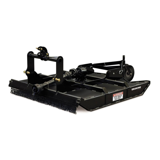
- Page 1 3-Point Brush Mower Compact Tractors Operator’s Manual Set-Up Assembly Maintenance Parts Information Read this Manual Before Use...
-
Page 2: Table Of Contents
Serial Number………….._____________ YOUR ATTACHMENTS DEALER ADDRESS: PHONE: CONTACT: NOTE: Erskine Attachments LLC reserves the right to make improvements in design or changes in specifications at any time without notice and without incurring any obligations to install them on units previously sold. -
Page 3: Safety
Indicates potentially Erskine Attachments LLC cannot anticipate every hazardous situation which, if not avoided, possible circumstance that might involve potential will result in death or serious injury. hazard. The safety messages found in this manual ... - Page 4 NEVER place hands in the discharge area or clear debris while the engine is running. Do not modify equipment or add attachments that are not approved by Erskine Attachments LLC. Maintenance Use adequate safety warning lights and devices as ...
-
Page 5: Serial Number/Decal Location
SERIAL NUMBER AND SAFETY DECAL LOCATIONS Serial Number Location: It is important to refer to the serial number of the attachment when making repairs or ordering parts. Early or later models (identification made by serial number) may use different parts, or it may be necessary to use different procedures in doing a specific operation. - Page 6 Safety Decals Locations: The locations of the safety decals are shown. If Part number: 320359 these decals are missing, damaged, or painted over Location: Side of driveline shield they must be replaced. Call Erskine Attachments Quantity: 1 LLC (218-435-4045) for replacement decals.
-
Page 7: Set-Up Assembly
SET-UP ASSEMBLY Driveline Installation The attachment is shipped completely assembled with the exception of the driveline. The driveline must be installed prior to operation for the first time. 1. Position the attachment flat on the ground. 2. Remove both retaining bolts from the driveline. 3. -
Page 8: Mounting Instructions
MOUNTING INSTRUCTIONS After the initial set-up assembly is completed use the following procedure to mount the attachment to the compact tractor for user operation. 1. Use the step, safety treads, and grab handles to get on and off of the tractor. 2. -
Page 9: Instructions For Shortening The Driveline
INSTRUCTIONS FOR SHORTENING THE DRIVELINE The tractor must be equipped with working PTO shield. Never adjust or move the driveline when connected to the tractor and the tractor’s PTO drive is engaged to avoid serious injury or death. In some cases it will be necessary to shorten the PTO driveline to match your specific tractor. -
Page 10: Operating Instructions
OPERATING INSTRUCTIONS The type of brush being cut and the ground conditions will determine the best ground speed and cutting procedure. The attachment is designed to cut short or tall grass, brush, and small saplings. IMPORTANT: Before operating the attachment, perform service schedule... - Page 11 OPERATING INSTRUCTIONS Adjusting the Cutting Height The brush mower has four height settings, which can be adjusted using the following procedure. 1. Raise the attachment approximately 2 inches off of the ground. 2. Stop the engine and engage the park brake. 3.
- Page 12 OPERATING INSTRUCTIONS Backing Into Brush and Saplings The brush mower can be used in the reverse direction to mow over brush and small saplings. When using the brush mower in the reverse direction, move the tail wheel to the storage position to avoid damaging the wheel.
- Page 13 _____________________ROUTINE MAINTENANCE________________ Lower the attachment to rest flat on the ground, disengage the PTO, set the park brake, shut down the engine, remove the key, and wait for all motion to stop before leaving the operator’s seat to perform service of any kind. It is the operator’s responsibility to make daily inspections of the tractor and attachment for damage, loose bolts, fluid leaks, or anything else that could cause a potential service or safety problem.
-
Page 14: Routine Maintenance
ROUTINE MAINTENANCE Gearbox Fluid Check and Fill Add 80W-90 EP or 85W-140 EP gear lube to gearbox as needed. Oil capacity is approximately 33 oz. To check the oil level, position the attachment flat on the ground, stop the engine, and engage the park brake. - Page 15 ROUTINE MAINTENANCE Blade Removal and Installation NOTE: Refer to “Daily Inspection” on page 13 of this manual for daily maintenance check. Check that the blades can swing freely. Also check blades, mounting hardware, and stump jumper for wear, cracking, or breakage, which can cause excessive vibrations.
- Page 16 ROUTINE MAINTENANCE Cleaning the Brush Mower 1. Position the brush mower flat on the ground, stop the engine, and engage the park brake. 2. Disconnect the driveline from the tractor PTO shaft. Always wear eye protection that meets ANSI z87.1 standard when cleaning the attachment.
-
Page 17: Bolt Torque Information
BOLT TORQUE INFORMATION... -
Page 18: Parts Information
FRAME TAIL WHEEL 1.00” W/A OLD STYLE ONLY 314162 FLEX LINK W/A 314059 STUMP JUMPER W/A 314109 KIT PARTS BLADE 60" MOWER 314110 KIT PARTS BLADE 72" MOWER 314064 BOLT MOWER BLADE 1/2 THICK 314061 WASHER HARD 1.25 ID X 4.438 OD... - Page 19 3PT BRUSH MOWER PARTS INFORMATION Add 33oz of 80W-90...
- Page 20 3PT BRUSH MOWER PARTS INFORMATION ITEM PART NO. DESCRIPTION STOCK NO. 300711 WHEEL ASSM 15 X 4 LAMINATED W/FORK 330834 FORK TAILWHEEL COMES IN ASSY 300711 330835 WHEEL LAMINATED 15 X 4 COMES IN ASSY 300711 330836 HUB W/BUSHINGS TAILWHEEL COMES IN ASSY 300711 330837 BUSHING OILITE 1"...
-
Page 21: General Specifications
GENERAL SPECIFICATIONS Model 60” 72” Cutting Width Hitch Category Cat. I Cat. I & Cat. II Input Speed 540 RPM Tractor PTO HP 35-50 40-75 Operating Weight 920 lbs. 1,170 lbs. All dimensions are in INCHES. -
Page 22: Notes
NOTES ____________________________________________________ ____________________________________________________ ____________________________________________________ ____________________________________________________ ____________________________________________________ ____________________________________________________ ____________________________________________________ ____________________________________________________ ____________________________________________________ ____________________________________________________ ____________________________________________________ ____________________________________________________ ____________________________________________________ ____________________________________________________ ____________________________________________________ ____________________________________________________ ____________________________________________________ ____________________________________________________ ____________________________________________________ ____________________________________________________ ____________________________________________________ ____________________________________________________ ____________________________________________________ ____________________________________________________ ____________________________________________________ ____________________________________________________ ____________________________________________________ ____________________________________________________ ____________________________________________________ ____________________________________________________ ____________________________________________________ ____________________________________________________ ____________________________________________________... -
Page 23: Warranty
Erskine Attachments LLC to improve its products whenever it is possible and practical to do so. Erskine Attachments LLC reserves the right to make changes and or add improvements at any time without incurring any obligation to make such changes or add such improvements to products previously sold. - Page 24 P/N 300534 Date Printed: 11/2/2018 Printed in U.S.A. Erskine Attachments LLC...
Need help?
Do you have a question about the 60 and is the answer not in the manual?
Questions and answers