
Related Manuals for Jensen WOODCHIPPER


Summary of Contents for Jensen WOODCHIPPER
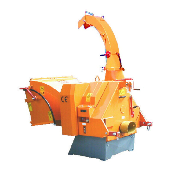
- Page 1 WOODCHIPPER Operating instructions List of spare parts Type : A240 ZKX Machine Nr.: 220703541 Date of building : 03/2007 Jensen Service GmbH D- 24975 Maasbüll Tel.: 04634 / 9370-0 Fax: 04634 / 1025 E-mail: info@jensen-service.de...
- Page 3 Before attempting any maintenance on the machines, read the instruction and safety manuel thouroughly. We are always striving to improve our product and we reserve the right to bring about any changes and improvements which we consider to be appropriate. An obligation to any previously delivered machines and extended apparatus is ínvalid.
- Page 5 At the side of the instruction manual, on the application and on the insert there are binding regulations concerning accident prevention and the recognised technical rules for safety which must be complyed with. We wish you much success with the use of our machine in your work. Jensen Service.
- Page 7 Konformitätserklärung Certificate of CE conformity Déclaration de conformité JENSEN Holzhackmaschinen GMBH Bahnhofstraße 20-22 D-24975 Maasbüll bestätigt hiermit, dass die von ihr hergestellte Maschine (Holzzerkleinerer) declares that the manufactured machine (wood chipper) déclare que la machine fabriquée (broyeur de branches) A 240 Z...
- Page 9 Bedeutung der Piktogramme Meaning of the pictograms Signification des pictogrammes Betekenis van de pictogrammen Piktogramme Bedeutung Position Pictogramm Meaning Place Pictogramme / Pictogrammen Signification / Betekenis Positionnement / Positie Vor Inbetriebnahme die Betriebs- anleitung und Sicherheitshinweise lesen und beachten. Service - Center Carefully read operator’s manual before Service - Center handling the machine.
- Page 10 Bedeutung der Piktogramme Meaning of the Pictograms Signification des pictogrammes Betekenis van de pictogrammen Piktogramme Bedeutung Position Pictogram Meaning Place Pictogramme / Pictogrammen Signification / Betekenis Positionnement / Positie Gefahr durch sich drehende Maschinen- teile. Alle Maschinen je 1x Keep away from rotating machine parts. rechts u.
- Page 11 Bedeutung der Piktogramme Meaning of the pictograms Signification des pictogrammes Betekenis van de pictogrammen Piktogramme Bedeutung Position Pictogram Meaning Place Pictogramme / Pictogrammen Signification / Betekenis Positionnement / Positie Gefahr durch fort schleudernde Teile bei laufendem Motor – Sicherheitsabstand halten. Trog rechts Danger –...
- Page 12 Bedeutung der Piktogramme Meaning of the pictograms Signification des pictogrammes Betekenis van de pictogrammen Piktogramme Bedeutung Position Pictogram Meaning Place Pictogramme / Pictogrammen Signification / Betekenis Positionnement / Positie Schaltstellungen Stop – Einzug - Rückwärts Switch position Stop – Input – backwarts Trog rechts Right side from infeed chute Positionnement du commutateur...
- Page 13 GENERAL SAFETY AND ACCIDENT PREVENTION INSTRUCTIONS With variations in machines, some of these statements may be contradictory as regards the servicing. In these cases it is advisable to follow the standard guidelines! Basic rules: Before anyone starts up the wood chipper study the safety rules for commerce and operation! Pay attention to the references in this operations guide as they are general legal safety and accident prevention instructions.
-
Page 14: Starting Instructions
On transport routes take precautionary safety measures to ensure that revolving pieces of equipment do not dangerously alter the area! Ensure that construction equipment/personnel are standing in a safe place! Additional weights In the construction of the Wood chipper, back and front propulsion is always sufficient for the load at the front and back respectively. - Page 15 Pay attention to the sliding clutch in the Cardan shaft and ensure that it is fully covered by the safety feature (machine and tractor) The covering of the safety features must be at least 50mm in total! Before turning on the PTO make sure that its high rotation speed power of the propulsion machine is equal to the permissible rotation speed of the Wood chipper! Before turning on the PTO take care that no one is in close enough proximity...
-
Page 16: Electrical Construction
In the event of the cap of the knife falling off, the chimney on that side will shake and stop! Only attempt the laying and removal of the V-belt when there is no movement! Safety features must be fitted according to the regulations! Safety preparations such as welding, sharpening, drilling etc. - Page 17 Hydraulic construction. Stop the permitted opperations pressure! The hydraulic structure is kept under high pressure! Under the high pressure it is possible that some of the high pressure fluids may escape (hydraulic oil). This is able to penetrate the skin and can cause serious injuries.
- Page 18 General work safety references. The wood chipper is built to the very highest standards of engineering and is totally reliable. Despite this however, this product can also be dangerous when it is not operated according to the instructions. Every person who handles the fitting, works on, and tests the wood chipper, must have read and understood the entire instruction manual.
-
Page 19: Important Safety Precautions
The Jensen Woodchipper is designed for reducing shrubs, bushes, branches, orchard and vineyard prunings etc., of unlimited length. The machine is for mounting an a tractor 3- point linkage and may also be supplied on a single or twin axle chassis for trailed use. - Page 20 Suitable clothing Always wear - Safety helmet with face visor - Ear defenders - Thick gloves (Avoiding tight fitting gloves) - Overalls Avoid - Loose clothing - Ties - Anoraks with loose cords Starting the machine Always start with the feed rollers disengaged (‚stop‘ position). Start the tractor, and engage the PTO, building up to 540rpm gradually.
- Page 21 Caution! Take care! The machine has 60 liter Hydraulic oil in. Fuchs DEA Plantosyn 3268 ECO...
-
Page 22: Service Procedure
A425 / A428 / A430 / A328 / A340 = 35 Litres / minute A521 / A528 / A518 / A530 = 20 Litres / minute Greasing instruction Wood chipper Jensen For detailed greasing instructions and intervals, please refer to the sheet 'Greasing instructions' which is part of this operating instructions. - Page 23 Operating instructions Start of the machine = for tractor pivot shafts at 540 rpm clockwise rotation. Start machine at disengaged feeding and at slow pivot rotation. Disengage feeding: Push disengaging lever in direction knives-disc (position „AUS“) Engage feeding: Pull disengaging lever in opposite direction (position „EIN“) Recommended instructions during operation Branch wood to be fed always with heavier end towards retraction rollers.
- Page 24 Knife grinding overview with wear limit...
- Page 25 Depending from material to be chopped at minimum 9 HP (6,6 KW) Attention: Use only spare parts origin JENSEN. No warranty in case of using other products. In case of spare part order always mention the number of this machine.
-
Page 26: Important! Additional Information
IMPORTANT! ADDITIONAL INFORMATION Combination of tractor and mounted implement The mounting of implements on the front or rear three point linkage shall not result in exceeding the maximum permissible weight, the permissible axle loads and the tyre load carrying capacities of the tractor. The front axle of the tractor must always to be loaded with at least 20% of the unladen weight of the tractor. - Page 27 IMPORTANT! ADDITIONAL INFORMATION Combination of tractor and mounted implement CALCULATION OF THE REAL FRONT AXLE LOAD T F real (If with the front mounted implement (I ) the required minimum front ballasting (I ) cannot be reached, F min the weight of the front mounted implement has to be increased to the weight of the minimum ballasting at the front!) Record the calculated real front axle load and the permissible front axle load of the tractor into the table.
- Page 28 dB(A) – ratings for different machine types Type of dB(A) at measuring point machine Last Leerlauf A 041/141 Di A 041/141 Z A 231/240 Di A 231/240 Z A 328/340 Di A 328/340 Z A 328/340 ZUX 103 A 325 Di A 325 Z A 325 ZUX A 425/430 Di...
- Page 29 Greasing Instruction A231/A240 Greasing instructions for 8-working-hours-shift Frequency of Quantity of lubricant, Pos. No. Designation Quantity lubrication strokes of grease gun Main shaft bearing monthly 3-4, Retinax A free of spur gears SAE 85 W 140 maintenance joint every 16 hours 2-3, Retinax A telescopic section every 16 hours...
- Page 30 KTR-N 40818 E ® KTR Kupplungstechnik C L A M P E X K T R 4 0 0 sheet: GmbH m o u n t i n g i n s t r u c t i o n s D-48407 Rheine edition: ®...
- Page 31 KTR-N 40818 E ® KTR Kupplungstechnik C L A M P E X K T R 4 0 0 sheet: GmbH m o u n t i n g i n s t r u c t i o n s D-48407 Rheine edition: The clamping set is generally delivered in assembled condition.
- Page 32 KTR-N 40818 E ® KTR Kupplungstechnik C L A M P E X K T R 4 0 0 sheet: GmbH m o u n t i n g i n s t r u c t i o n s D-48407 Rheine edition: Assembly...
- Page 33 KTR-N 40818 E ® KTR Kupplungstechnik C L A M P E X K T R 4 0 0 sheet: GmbH m o u n t i n g i n s t r u c t i o n s D-48407 Rheine edition: Disassembly...
- Page 34 Joint Clean PTO shaft. Operate quick- Connecting Actuate locking disconnect lock. Pull on the PTO drive or push depending shaft. on lock model. Wide-angle CV PTO For excessive Joint drive shaft articulations, articulation stop PTO shaft. Check joint articulation in operation and standstill 1.
- Page 35 Joint Dismantling Place joint as shown above and use light hammer blows to drive Remove retaining ring. up bearing bush. As a function of size, fix bearing bush into spezial tool SW23 or SW27 and remove bearing bush by light hammer blows onto the yoke or by rotating it.
- Page 36 Automatic overload regulator Accessories Rotational speed display for service and operation. You can connect an external display on the terminal block X4 to display the actual rotational speed. Technical Data Nominal voltage From 12V DC – or 24V DC – on-board system with diesel generator set running.
- Page 37 Automatic overload regulator Mounting of the pulse pick-up: For optimum functioning the following mounting dimensions should be adhered to: max. 2mm Setting must always be greater than D Operation Check the safe functioning of the unit. If operation is correct no special measures need to be taken nor any measures for maintenance an upkeep.
- Page 38 DC 104 - 12V DC 104 - 12V Electrical connexion for automatic overload regulator Electrical connexion for automatic overload regulator With magnetic valve closed when de-energised With the Jumper (1) the electric re-set Jumper (1) bridged, without Jumper (1) non-bridged, with bottons or pushbuttons can be activated or electric re-set button or pushbuttons electric re-set button or pushbuttons...
- Page 39 Original – Ersatzteile Original - spare parts Pièces de rechange d’origine...
- Page 40 Hydraulikanlage Hydraulic system Circuit hydraulique Die mit einem "+" gekennzeichneten Teile sind nicht abgebildet! Parts marked "+" are not shown in figures! Les positons précédées du signe "+" ne sont pas représentées!
- Page 41 Hydraulikanlage Hydraulic system Circuit hydraulique Pos. Nr.: Bestell Nr.: Bezeichnung Designation Designation Anzahl Fig. Nr.: Order Nr.: pcs. Fig. Nr.: Ordre Nr.: pcs. 21199 Hydraulik - Schlauch tube tuyeau 19198 Hydraulik - Schlauch tube tuyeau 19040 Hydraulik - Schlauch tube tuyeau 9556 Hydraulik - Schlauch...
- Page 42 Pumpenantrieb hydraulic pump drive Propulsion pour pompe hydraulique Pos. Nr.: Bestell Nr.: Bezeichnung Designation Designation Anzahl Fig. Nr.: Order Nr.: pcs. Fig. Nr.: Ordre Nr.: pcs. -------- Hydraulik Pumpe hydraulic pump Pompe hydraulique (Siehe Hydraulikplan) (see hydraulic sheet) (voyez plan hydr.s.v.p) 7072 Schraube screw...
- Page 43 A231 Vorgelege Reduction Gear Reducteur Die mit einem "+" gekennzeichneten Teile sind nicht abgebildet! Parts marked "+" are not shown in figures! Les positons précédées du signe "+" ne sont pas représentées!
- Page 44 A231 Vorgelege Reduction Gear Reducteur Pos. Nr.: Bestell Nr.: Bezeichnung Designation Designation Anzahl Fig. Nr.: Order Nr.: pcs. Fig. Nr.: Ordre Nr.: pcs. 15129 Schraube screw boulon 2175 Federring spring ring rondelle elastique Endscheibe plate disque d' extremite 1351 Flanschzapfen flange flange 14 603...
- Page 45 Keilriemenberuhigungsrolle Roller for V-belts Galet tendeur pour courroies Pos. Nr.: Bestell Nr.: Bezeichnung Designation Designation Anzahl Fig. Nr.: Order Nr.: pcs. Fig. Nr.: Ordre Nr.: pcs. 25039 Sechskantschraube Screw 3054 Sicherungsscheibe Retaining washer Joint d'arret Endscheibe End disc Rondelle d´arrêt Rillenkugellager Grooved ball bearing Roulement à...
- Page 46 Hauptwelle Main Shaft Arbre Principal 08.03.2006 Hauptwelle A231 ZKX 6-rillig 200ter 3_Sprachen.xls...
- Page 47 Hauptwelle Main Shaft Arbre Principal Pos. Nr.: Bestell Nr.: Bezeichnung Designation Designation Anzahl Fig. Nr.: Order Nr.: pcs. Fig. Nr.: Ordre Nr.: pcs. 2377 Spannsatz clamping set elément de serrage 40085 Keilscheibe pulley poulie 2053 Buchse bushing prise femelle 14621 Keilscheibe pulley poulie...
- Page 48 2-Messerscheibe chipper disc Volant Bauartbedingte Bildabweichung möglich! Deviations from figures possible! Differences symboliques possibles!
- Page 49 2-Messerscheibe chipper disc Volant Pos. Nr.: Bestell Nr. Bezeichnung Designation Designation Anzahl Fig. Nr.: Order Nr.: pcs. Fig. Nr.: Ordre Nr.: pcs. 17114 2-Messer-Fensterscheibe Window disc Volant à fenêtres 1999 Schraube screw boulon 1998 Mutter ecrou 22109 Mutter ecrou 9183 Schnorrsicherung washer rondelle elastique...
- Page 50 Walzenantrieb Roller drive Transmission à rouleau Pos. Nr.: Bestell Nr.: Bezeichnung Designation Designation Anzahl Fig. Nr.: Order Nr.: pcs. Fig. Nr.: Ordre Nr.: pcs. 16831 Getriebe Transmission Transmission 16987 Gelenk kpl. joint cplt. fourche d' articulation cpl. 10014 Spannstift spring pin clavette 10014 Spannstift...
- Page 51 Obere Walze Upper roller Roleau superieure Pos. Nr.: Bestell Nr.: Bezeichnung Designation Designation Anzahl Fig. Nr.: Order Nr.: pcs. Fig. Nr.: Ordre Nr.: pcs. base spring ressort de traction 10447 Zugfeder hexagon nut écrou six-pans 3305 Skt.-Mutter 17056 pressure bar bouterolle de pression Druckbalken washer...
- Page 52 Untere Walze Upper roller Roleau supérieur Pos. Nr.: Bestell Nr.: Bezeichnung Designation Designation Anzahl Fig. Nr.: Order Nr.: pcs. Fig. Nr.: Ordre Nr.: pcs. pillow block palier Stehlager paralell key clavette plate 6155 Passfeder inferior roller rouleau inferieure 17133 untere Walze inferior roller shaft arbre inferieure 17500...
- Page 53 A231 Auswerfer, starr Ejector Goulotte d' éjection Pos. Nr.: Bestell Nr.: Bezeichnung Designation Designation Anzahl Fig. Nr.: Order Nr.: pcs. Fig. Nr.: Ordre Nr.: pcs. 16356 Auswerfer, kpl. ejector cpl. Goulotte d' éjection complète 16978 Auswurfklappe adjustable trab clapet articulè 10134 Mutter écrou...
- Page 54 Jensen Service GmbH Bahnhofstraße 20-22 D-24975 Maasbüll Tel.: 04634 / 9370-0 Telefax: 04634 / 1025 eMail: info@jensen-service.de http://www.Holzhackmaschinen.com...
Need help?
Do you have a question about the WOODCHIPPER and is the answer not in the manual?
Questions and answers