
Related Manuals for Autometers Systems HORIZON HT-35


Summary of Contents for Autometers Systems HORIZON HT-35
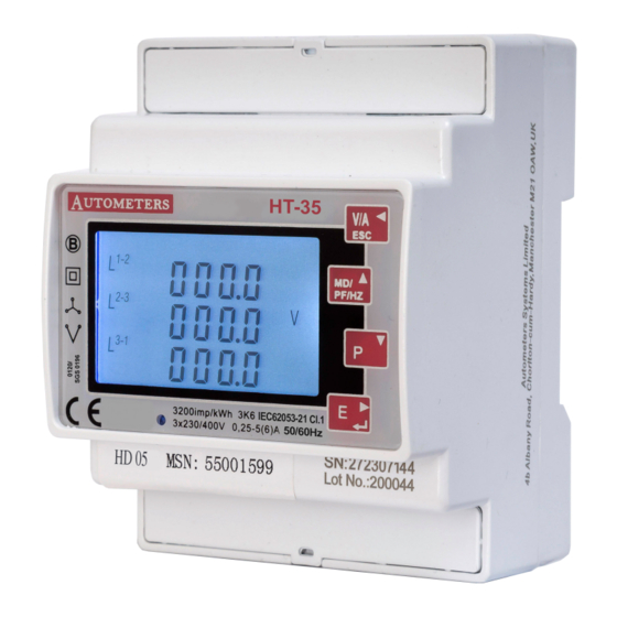
- Page 1 Energy Monitoring and Invoicing HORIZON SYSTEM METER HT-35 Multi Function , Multi Tariff , MID Approved. Autometers Modbus V6.
- Page 2 Introduction....................... 1. Unit Characteristics..................... 1.1 Unit Characteristics 1.2 RS485 Serial Modbus RTU 1.3 Pulse Output 2. Start-up Screens 2.1 Reading an 8 digit kWh register number 3. Keys and Displays....................3.1 Button Functions 3.2 Voltage and Current..................3.3 Frequency and Power Factor and Demand 3.4 Power 3.5 Energy Measurements...................
-
Page 3: Declaration Of Conformity
Horizon data monitoring and invoicing system Declaration of Conformity We Autometers Systems Ltd declare under our sole responsibility as the manufacturer that the poly phase multifuntion electrical energy meter “HT-35 Series” correspond to the production model described in the EC-type examination certificate and to the... -
Page 4: Unit Characteristics
1. Unit Characteristics 1.1 Unit Characteristics MID Approved (SGS.UK) Appendix B and D Multi-tariff with internal time clock Measures kWh, KVArh, KVar,PF,Hz, Max demand RS 485 Modbus (Autometers V6 protocol) Two Pulse Outputs BI- Directional Measurement for Import and Export Back light LCD for full viewing Angles Available as 1 Phase 2 Wire, 3 Phase 3 Wire and 3 Phase 4 Wire Two pulse output indicate real-time energy measurement. -
Page 5: Keys And Displays
3. Keys and Displays Maximum Export Activation Pulse Import Demand indicator indicator buttons indicators indicator Tariff indicator Phase and Neutral indicators Total indicator Clock indicating tariffs are programmed (1-4) Import and Pulse indicator light Digital numbers Description energy readings Export icons 3.1 Button Functions Click Button... -
Page 6: Voltage And Current
3.2 Voltage and Current Each successive press of the button selects a new parameter: Phase to neutral voltages. Current on each phase. Phase to neutral voltage THD% of 2nd to 19th. Each phase Current THD% of 2nd to 19th. 3.3 Frequency and Power Factor and Demand Each successive press of the button selects a new range: PF/HZ... -
Page 7: Energy Measurements
3.5 Energy Measurements Each successive press of the button selects a new range: Imported Exported Imported Exported active reactive energy reactive energy active energy energy in kWh. in kVArh. in kVArh. in kWh. Tariff 1 active energy Date Time Tariff 2 active energy Year/month/day. -
Page 8: Menu Option Selection
4.1.1 Menu Option Selection Use the buttons to scroll through the different options of the set-up menu. PF/HZ Press to confirm your selection. If an item flashes, then it can be adjusted by the buttons. PF/HZ Having selected an option from the current layer, press to confirm your selection. - Page 9 4.3 DIT Demand Integration Time This sets the period in minutes over which the current and power readings are integrated for maximum demand measurement. The options are: 0, 5, 8,10,15, 20, 30, 60 minutes. From the set-up menu, use buttons to select the DIT PF/HZ option.
- Page 10 4.5 CT The CT option sets the secondary current (CT2 1A or 5A) of the current transformer (CT) that wires to the meter. From the set-up menu, use buttons to select the CT option. PF/HZ PF/HZ Secondary CT setting Press to enter the CT secondary current selection routine.:5A/1A Set CT Ratio value Press to enter the CT Ratio setting screen.
-
Page 11: Pulse Duration
4.7 Pulse Output This option allows you to configure the pulse output. The output can be set to provide a pulse for a defined amount of energy active or reactive. Use this section to set up the pulse output—Units: kWh/kVArh, import kWh/kVArh, export kWh/kVArh From the set-up menu, use buttons to select the Pulse PF/HZ... - Page 12 4.8.1 Modbus RS 485 Address (The range is from 001 to 247) From the set-up menu, use buttons to select the address ID. PF/HZ Press button to enter the selection routine. The current setting will be flashing. buttons to choose Modbus address (001 to 247). PF/HZ On completion of the entry procedure, press button to confirm the...
- Page 13 4.9 Backlit Set-up The meter provides a function to set the blue backlit lasting time (0/5/10/30/60/120 minutes). Option 0 means the backlit always on here. Default:60 If it’s set to 5,the backlit will be off in 5minutes. buttons to choose the time PF/HZ Press to confirm the setting and press...
-
Page 14: Specification
5. Specification 5.1 Measured Parameters The unit can monitor and display the following parameters of a single phase two wire(1p2w), three phase three wire(3p3w) or four phase four wire(3p4w) system. 5.1.1 Voltage and Current Phase to neutral voltages 100 to 276V a.c. (not for 3p3w supplies). Voltages between phases 173 to 480V a.c. -
Page 15: Reference Conditions Of Influence Quantities
The test pulse output is a polarity dependent, passive transistor output requiring an external voltage source for correct operation. For this external voltage source, the voltage (Ui) should be 5-27V DC, and the maximum input current (Imax) should be 27mA DC. To connect the impulse output, connect 5-27V DC to connector 7 (anode), and the signal wire(s) to connector 6 (cath- ode). -
Page 16: Maintenance
Water should not be used. If the rear case exterior or terminals should be contaminated accidentally with water, the unit must be returned to Autometers Systems Ltd for inspection and testing. -
Page 17: Emc Installation Requirements
8. Installation The meter is designed to be fitted on a DIN rail in a suitable enclosure. The unit is intended for use in a reasonably stable ambient temperature within the range -25°C to +55°C. Do not fit the meter where there is excessive vibration or in excessive direct sunlight. Please note terminal covers should be fitted and sealed. -
Page 18: Wiring Diagrams
11. Wiring Diagrams 3 phase 4 wire SHIELD TX- TX+ RS 485 Current inputs 10 11 12 13 14 15 16 17 18 19 20 S2 S1 S1 S2 Pulse Modbus IMPORTANT Current transformer P1 must face mains Voltage inputs 1A FAST BLOW FUSE 1A FAST BLOW FUSE LOAD... - Page 19 12. The Horizon Energy Monitoring System With the New HT-35 Series RS 485 Modbus Communication to enable full data retrieval of kWh for Graphic analysis and Billing Danger 415 Volts Isolate electricity supply before opening cover The HC2-P is a surface mounted GPRS enabled data collection device capable of storing information from up to 350 meters via 3 separate Lans 2 x Modbus –...
- Page 20 Danger 415 Volts Isolate electricity supply before opening cover www.autometers.co.uk UE-32 The UE-32 enclosure can accommodate up to 16 meters. Autometers Systems Ltd. 4B Albany Road, Chorlton-cum-Hardy Manchester M21 0AW Email: sales@autometers.co.uk Phone: 00(44) 0161 861 9056 Fax: 0161 881 3745 www.autometers.co.uk...
Need help?
Do you have a question about the HORIZON HT-35 and is the answer not in the manual?
Questions and answers