Advertisement
Quick Links
Autometers Systems Limited,
Tel: +44 (0) 161 861 9056
4B Albany Road,
Fax: +44 (0) 161 881 3745
Chorlton- cum-Hardy,
www.autometers.co.uk
Manchester.
Email: sales@autometers.co.uk
M21 0AW
24
Product development is continuous and Autometers
Systems Ltd reser ves the right to make alterations and
manufacture without notice. Products as delivered may
therefore differ from the descriptions and illustrations
in this publication.
Publication No. 23.09.2014
INSTALLATION
& OPERATING
MANUAL
Overview of the meter
The IC 970 is the latest meter in the IC 900 series
of Information Centres from Autometers Systems
Ltd. With new advances in micro processors and
new added features, the meters are user friendly,
easy to install and simple to programme.
The IC 900 range of Information Centres are electronic meters and great care has been taken to
ensure that they meet the stringent requirements of all the potential users and specifiers of the
product, from the buyer who wants a competitively priced product, the installer who wants
simple fitting with good connection terminals to the end user who wants a quick and easy means
of obtaining information. The IC 900 range of meters meets these varied demands.
The IC 970 meter has been designed to communicate with other systems by means of either pulse
outputs standard on all IC 900 meters or via a separate plug in communication module which is
sold with the meters or can be retro fitted at a later date.
All the IC 900 range of meters have been designed to communicate with Autometers Systems Ltd
Horizon range of data collection units, this enabling complete measurement and data collection
systems to be built up.
A new feature to the IC 970 is the protocol set up information which can be viewed on the display
when a communication module has been installed.
Pulse outputs
There are two optically isolated volt free relays outputs on the IC 970 and IC 990, one relay for
kWh and the other for kVah. Both these relays are fully programmable to adjust the value of the
pulse (4 settings) and the time of the contact closure. Both meters are factor y set to 1 imp/kWh
and 1 imp/kVah.
Communication module
An optional communication module can be fitted to the IC 970 and IC 990 meters offering a wider
range of information which can be transferred to a BMS system.
IC 970
1
Advertisement

Related Manuals for Autometers Systems IC 970


Summary of Contents for Autometers Systems IC 970
- Page 1 Horizon range of data collection units, this enabling complete measurement and data collection systems to be built up. A new feature to the IC 970 is the protocol set up information which can be viewed on the display when a communication module has been installed.
-
Page 3: Programming The Meter
Programming the meter To reset maximum demand - code 12 (view) When you receive the meter there will be at least one value that you must programme into the Please follow these instructions precisely. meter. This is the current transformer ratio. If you want to monitor the neutral current then the neutral current transformer ratio will also need to be programmed. - Page 4 To change the pulse output value To enter the C.T. Ratio code 13 (switch 8 on) Code 21 (switch 8 on) Your Current Transformer Ratio requires to be programmed into this meter. Please follow these Please follow these instructions precisely. instructions precisely.
- Page 5 To change the pulse closure time To change the display contrast Code 22 (switch 8 on) Code 30 (switch 8 on) Please follow these instructions precisely. Please follow these instructions precisely. 1. Press Function Key 1. Press Function Key The display will change to. The display will change to.
- Page 6 To change the time the back light is on To check the connections on the meter Code 31 (switch 8 on) Code 50 (view) Please follow these instructions precisely. Please follow these instructions precisely. 1. Press Function Key 1. Press Function Key The display will change to.
- Page 7 Indication of binary switch settings Relay test mode code 51 (switch 8 on) Code 52 (view) Please follow these instructions precisely. Please follow these instructions precisely. 1. Press Function Key 1. Press Function Key The display will change to. The display will change to. You will notice the cursor is flashing at the first digit on the left of the two digits You will notice the cursor is flashing at the first digit on the left of the two digits Press the key with 5 on it, the cursor will now move to the next digit now, press 1.
-
Page 8: Key Functions
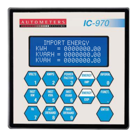
Instantaneous KVA Energy IMP (Default Screen) Key functions Display of 4 lines with Instantaneous KW Energy EXP The Information Key 20 characters per line. indicates how the meter has been programmed. Membrane Keypad The Function Key to with 15 sealed keys. select special functions. - Page 9 Programming the communication module Information key When you press the information key and the communication module is fitted the following displays You will notice in the picture below two red ver tical rows of switches 1 - 8. Above each row the will appear.
-
Page 11: Transformer Selection
In this case the C T size should be the maximum expected peak current +25%, rounded up to the nearest standard C T size. There are two optically isolated volt free relays on the IC 970. O ther factors may affect C T accuracy. The length of the C T cabling should be minimised. - Page 12 CE Approval. Field Service Considerations The IC 970 has been fully examined and tested in accordance with the standards listed and meets the specified requirements defined in BS EN 61326:1997 inc A1, A2, A3 - Electrical equipment for In the unlikely event that a unit should fail, it will generally be ser viced by exchanging the unit measurement, control and laborator y use - EMC requirements.
Need help?
Do you have a question about the IC 970 and is the answer not in the manual?
Questions and answers