
Subscribe to Our Youtube Channel
Related Manuals for Autometers Systems HORIZON HT-1095


Summary of Contents for Autometers Systems HORIZON HT-1095
- Page 1 Energy Monitoring and Invoicing HORIZON SYSTEM METER HT-1095 Multi Function , Multi Tariff , MID Approved. Autometers Modbus V6.
-
Page 2: Table Of Contents
Contents Introduction ..........................1. Unit characteristics ......................1.1 Measuring and display ....................1.2 Password protection ....................1.3 CT and PT ........................1.4 RS485 Serial Modbus RTU ..................1.5 Pulse output ....................... 2. Start up screens ........................3. Keys and displays ........................ -
Page 3: Introduction
Introduction The HT-1095 is a multifunction energy analyzer and is the latest in a new generation of MID approved intelligent panel meters used not only in the electricity transmission and power distribution system, but also in the power consumption measurement and analysis in high voltage intelligent power grid. -
Page 4: Unit Characteristics
1. Unit Characteristics 1. 1 The Unit can measure and display: Line voltage and THD% (total harmonic distortion) of all phases 2~63rd voltage IHD% (Individual Harmonic distortion) of all phases Line Frequency Currents, Current demands and current THD% of all phases 2~63rd current IHD% of all phases Active power, reactive power, apparent power, maximum power demand and power factor Active energy imported and exported... -
Page 5: Start Up Screens
2. Start up screens The first screen The second screen The unit performs a After a short delay, lights all LED indicates the self-test and the the default segments and can software version of screen indicates if measurement be used as a the unit. -
Page 6: Display Mode Screen Sequence
3.2 Display Mode Screen Sequence Click button 3 Phase 4 Wire 3 Phase 3 Wire 1 Phase 2 Wire Screen Parameters Screen Parameters Screen Parameters Phase 1 – Power Phase 1 – Power Phase 1 – Power Voltage Current Voltage Ph S Current Current... - Page 7 Click button 3 Phase 4 Wire 3 Phase 3 Wire 1 Phase 2 Wire Screen Parameters Screen Parameters Screen Parameters Total Power Factor Total Power Factor Total Power Factor Frequency Frequency Frequency PF Hz PF L1 PF L1 PF L2 PF L2 PF L3 PF L3...
-
Page 8: Individual Harmonic Distortion
Click button 3 Phase 4 Wire 3 Phase 3 Wire 1 Phase 2 Wire Screen Parameters Screen Parameters Screen Parameters Import kWh Import kWh Import kWh Export kWh Export kWh Export kWh Import kVarh Import kVarh Import kVarh Export KVarh Export KVarh Export KVarh T1 import kWh... -
Page 9: Display Information
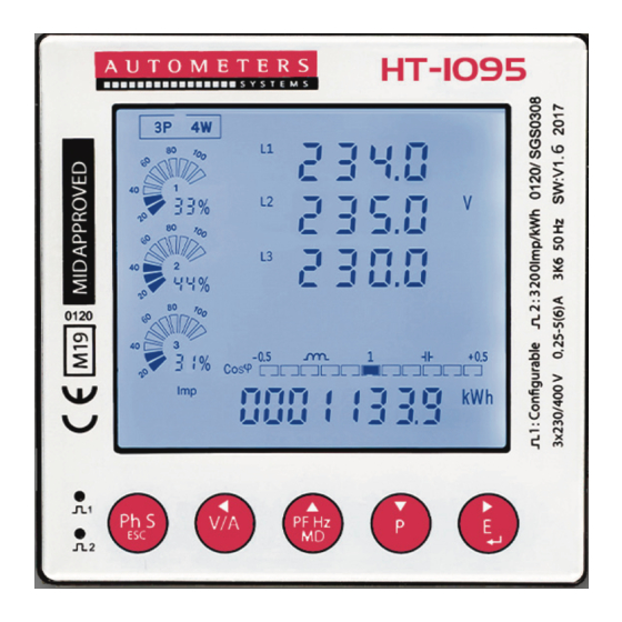
4. Display information Phone symbol on when Description on energy Pulse Outputs being monitored. communicating (Modbus) Individual phases and Neutral. Network system programmed into the meter Description of instantaneous Energy, Pf, Hz and Harmonics readings per phase. Circular graph indicating percentage of load flowing on each phase. -
Page 10: Programming The Meter
5. Programming the meter Main screen Password Entry COMS (Communication) Addr (Address) Entry Value between: 1~247 bAUd (Baud rate) Select from: (bps) 2400 4800 9600 19.2k 38.4k PArI (parity) Select from: NONE EVEN CT (System Configuration) Select from: CT rAtE (when CT2=5A/1A) Entry CT Ratio Value between: 1~2000 CT1 (When CT2=0.1A/0.333V... -
Page 11: Password Entry
5.1 Password Entry Setting-up mode is password protected, so you must enter the correct password. By firmly pressing the button for 3 seconds, the password screen appears. The default password is 1000. If an incorrect password is entered, the display shows ERR. 5.2 Communication The RS485 port can be used for communications using Modbus RTU protocol. -
Page 12: Parity
5.2.3 Parity Parity Options: NONE, EVEN, ODD. Default Parity : EVEN PF Hz From the Set-up menu, Use to select the Parity options. Long Press to enter the selection routine. PF Hz The Parity setting will flash. Use to choose Parity. Example shows: Set Parity: EVEN And long press... -
Page 13: Example Of A Meter Set At 200/5Amp
5.3.3. Example of meter set at 200/5 amp Example of how the display should look for a meter programmed to 200/5 amp. See table for more settings. C.T Primary Number to program into C.T Primary Number to program into the meter the meter 100/5 800/5... -
Page 14: Pulse
5.5 Pulse This option allows you to configure the pulse output. The output can be set to provide a pulse for a defined amount of energy active or reactive. This option sets the pulse output type, pulse rate, duration time. PF Hz From the Set-up menu, Use to select the Pulse option. -
Page 15: Pulse Duration
5.5.3 Pulse Duration Pulse Duration time option 200, 100, 60mS Default : 100mS PF Hz to enter Pulse duration routine. PF Hz Long press , the setting will flash. Use to choose Options. And long press for confirmation. Ph S Press to return the Pulse Duration set up menu. -
Page 16: Back Light Display Time Setting
5.7 Back light display time setting. This option sets the backlight on time and display scroll time. PF Hz From the Set-up menu, Use to select the Time option. 5.7.1 Backlight time The meter provides a function to set the time the back light is on. Options: ON/OFF/5/10/30/60/120 minutes. -
Page 17: Set Tariff
PF Hz Press the hour will flash. Use to choose correct value. Short press to confirm and move to minutes. Use PF Hz choose correct value. Short press to confirm and move to seconds. PF Hz to choose the correct value. Long press confirm. -
Page 18: System Network
5.8.1 System Network The screen shows the currently selected power supply is three phase four wire Long press to enter the System type routine. Long press , the setting will flash. Use to choose Options. PF Hz And Long press for confirmation. -
Page 19: Change Password
5.8.3 Change password This meter provides a function with password setting. Default: 1000 Options:0000~9999 PF Hz to select the change password option. Long press , the setting will flash. PF Hz to increment the number. Press to choose options. Long press for confirmation. -
Page 20: Parameter Reset
5.9 Demand reset This meter provides a manual reset of the various demands available. Long press to enter Demand Reset routine. Long press , dnd will flash. Long press to confirm the reset. The display will show Re-set Good. This acknowledges the reset is confirmed. Press twice to return to the main display. -
Page 21: Specification
6. Specification 6.1 Measured Parameters The unit can monitor and display the following parameters of a 1 phase 2 wire, 3-phase 3-wire or 3-phase 4-wire supply. 6.1.1 Voltage and Current Rated Voltage Input: 3x230/400V 50Hz Installation Category III (600V) Rated Current: 5A Current input range: 5%~120% Ib Percentage total voltage harmony distortion (THD %) for each phase to N Percentage current harmonic distortion for each phase... -
Page 22: Pulse Output
6.1.6 Pulse Output The pulse outputs can be set to generate pulses to represent kWh/kVarh Pulse constant: 0.001/0.01/0.1/1/10/100/1000 kWh or kVarh per Pulse Pulse width: 200/100/60 Ms. The pulse output is passive type, complies with IEC62053-31 Class A. ATTENTION: Pulse output must be fed as shown in the OUTPUT wiring diagram below. -
Page 23: Maintenance
Water should not be used. If the rear case exterior or terminals should be contaminated accidentally with water, the unit must be returned to Autometers Systems Ltd for inspection and testing. -
Page 24: Dimensions
Screened communication leads are recommended and may be required. These and other connecting leads may require the fitting of RF suppression components, such as ferrite absorbers, line filters etc., if RF fields cause problems. It is good practice to install sensitive electronic instruments that are performing critical functions in EMC enclosures that protect against electrical interference causing a disturbance in function. -
Page 25: Wiring Diagram
12. Wiring Diagram It is imperative that the current transformers are of the correct accuracy, fitted correctly and the meter is programmed to match the current transformers ratio. 3 phase 4 wire Direction of Current Neutral MODBUS OUTPUT TX+ TX- SHIELD 1 Amp Fast Blow Fuses... -
Page 26: Metal Enclosures For The Ht-1095
Declaration of Conformity for the HT-1095 Panel Meter. We, Autometers Systems Ltd, declare under our sole responsibility as the manufacturer of the HT-1095 that the three phase four wire multifunction electrical energy meter “HT-1095” series correspond to the production model described in the EU-type examination certificate and to the requirements of the directive 2014/32/EU type examination certificate number 0120/SGS0308. -
Page 27: The Horizon Energy Monitoring System With The Ht-1095
15. The Horizon Energy Monitoring System with the new HT-1095 RS 485 Modbus Communication to enable full data retrieval of kWh for Graphic analysis and Billing Danger 415 Volts Isolate electricity supply before opening cover The HC2-P is a surface mounted GPRS enabled data collection device capable of storing information from up to 350 meters via 3 separate Lans 2 x Modbus –... - Page 28 Autometers Systems Ltd. 4B Albany Road, Chorlton-cum-Hardy Manchester M21 0AW Email: sales@autometers.co.uk Phone: 00(44) 0161 861 9056 Fax: 0161 881 3745 www.autometers.co.uk Product development is continuous and Autometers Systems Limited reserves the right to make alterations and manufacture without notice. Products as delivered may therefor differ from the descriptions and illustrations in this...
Need help?
Do you have a question about the HORIZON HT-1095 and is the answer not in the manual?
Questions and answers