
Subscribe to Our Youtube Channel
Related Manuals for Graphic Whizard PT 335B Multi


Summary of Contents for Graphic Whizard PT 335B Multi
- Page 1 PT 335B Multi Automatic Creaser Operator Manual 755 Griffith Court, Burlington, Ontario, Canada L7L 5R9 Tel: +(905) 633-7663 Fax: +(905) 637-4419 Toll Free: 1-800-265-3376 www.graphicwhizard.com...
-
Page 2: Table Of Contents
10/20/2020 Table of Contents Introduction ............................2 Important Information ........................2 Safety Precautions ........................... 3 Specifications ........................... 4 Parts and Assemblies ........................5 Installation ............................7 Uninstall the Protection Bar ......................7 Exit Tray, Stops and Guides ......................7 Feed Tray Extension ........................8 Power Socket and Switch ...................... -
Page 3: Introduction
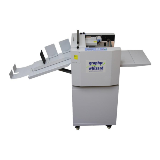
13” x 25.5”. With a maximum of 32 crease/perf positions per sheet, 30 job memory, and speeds up to 4,500 SPH, the PT 335B Multi is a capable and affordable finishing option. -
Page 4: Safety Precautions
Safety Precautions Please read this entire manual before attempting to operate the PT 335B Multi. • DO NOT operate the machine when any covers are removed, or safety switches disabled. The machine should be serviced only by qualified personnel. Obey all safety instructions and warning labels. Graphic Whizard Inc. -
Page 5: Specifications
Specifications Item Spec Electrical 110-130V, 50/60Hz, 15A 4,500 SPH Speed (based on 8.5”x11” run landscape, 1 crease) Maximum Stock Size 13”x25.5“ Minimum Stock Size 4.7”x 5.5” Stock Weight 26# bond – 16 pt. Tabletop (image on previous page; machine shown Tabletop/Floor Model with optional stand) Maximum # Crease Positions... -
Page 6: Parts And Assemblies
Parts and Assemblies 10 11... - Page 7 Parts Description Slide-In Bar Lock Crease/Perf bar entry lock Slide-In Bar Crease bar or perforation bar Handle Crease/Perf bar handle Stand Optional with casters Power Socket For system power Power Switch On/off Feed Table Extension To load longer sheets Paper Stop To hold the paper when it is feeding Fixed Side Guide For skew adjustment...
-
Page 8: Installation
Installation Uninstall the Protection Bar Ensure all brackets are removed for shipping purposes (see images below). There should not be any brackets installed holding the feed table down once set up begins. During shipping there will be a support bar installed across the feeding table, as well as a small bracket holding the table down. -
Page 9: Feed Tray Extension
Feed Tray Extension There are 2 screws on the tail of the feeding table (Figure A), and there are 2 holes on the side of the extension table (Figure B). Align and secure. Figure B Figure A Power Socket and Switch Before using the machine, ensure that the electrical output at the source is adequate for the machine specifications. -
Page 10: Fuses
Fuses If there is a power surge, or the power exceeds machine requirements and the fuse requires replacing, the fuse is housed beneath the power socket. **Ensure power is disconnected before performing any maintenance. -
Page 11: Quick Start
Quick Start (See machine diagram for parts listing) 1. Turn on machine. 2. To lower tray, press STOP. 3. Put stock in the feed tray, against the fixed guides, front and side. The paper guides (pillars) and back stop work together to keep the paper aligned and from slipping out of the feeder. 4. - Page 12 12. For thin paper you may need to use 1 or 2 magnetic deflectors to stop the paper from lifting. 13. Programming a Crease Job: • Turn on machine. Screen 1 will appear after the welcome page Screen 1 Screen 2 •...
-
Page 13: Operation
Operation Control Panel The control panel consists of a keypad and screen, as per the following diagram. Description Stop Stop the machine. Start Run the machine. Test Machine will stop after one sheet. Clear Clear the data or clear the error display. Numbers Input data. -
Page 14: Function And Operation
Function and Operation Turn on the machine. A welcome page will appear which will last for approximately 2 seconds, then jump to operation mode automatically. All system screens are divided into 5 MODES as per different functions. Scroll through the modes by pressing the mode key M. In each MODE, there may be more than 1 page to display different information. - Page 15 • Initially in Mode 2, Line [1] flashes (which means data can be input). Input the data from 0-900.0 (accurate to one decimal place). • Press ENTER, [1] will stop flashing, [2] will begin flashing. • Input data, press ENTER. stop flashing, screen automatically jump to 2nd page.
- Page 16 MODE 3 Cover Hinge This is a mode specifically for book cover making. The following is an explanation of the setup and function of this mode, in which you can input 2 parameters. SPINE and THK. SPINE means the first spine line to the leading edge. THK means the thickness of the book, namely the spine width.
- Page 17 MODE 4 Progressive Crease If you want to shut down the function, press 1, then Enter. Screen will jump to the main operation mode. If you want to activate the function, press 2, then Enter. Screen will jump to the following to input settings for the progressive crease:...
- Page 18 If all the sheets are creased on same position, the bounded book cannot be turned over to lay flat like this drawing. With 3 crease modes, even thick paper can be turned over very easily and lay flat after binding. The illustration for V mode is as follows: Define the first position and crease gap and the qty in one batch.
- Page 19 With Progressive Crease function is activated and all input is completed, the screen will jump to the main operation mode. But the screen is different, and it has only 1 page as follows: Press M, go to MODE 5. Press M again, go to MODE 6. MODE 5 Feed Mode The user can choose Auto feeding mode or Manual feeding mode.
- Page 20 1. How to save a job • See MODE 2. Let us input a job, i.e. 10, 20, 30, 0, 0, 0. • Press M button 2 times to go to Save Job Mode. • Input a number between 1-30, i.e. 1. Screen changes into: •...
- Page 21 Note: It is advisable for users to record the job numbers in memory to avoid overwriting previously saved jobs. Press M button 5 times and the machine will advance to MODE 7. MODE 7 Speed 1. For LOW speed, press 1. The “*” will indicate “Low.” Press Enter, the screen will jump to main operation MODE and low speed is chosen.
-
Page 22: Hardware Setting
Hardware Setting Crease Depth Crease depth is important to overall crease quality. Depth should be adjusted according to the paper thickness. Low depth will perform an unclear crease, but a heavy depth may cause cracking, or cause the system to take it as a double feed. An adjustment is also needed if the crease depths are not balanced on both sides. -
Page 23: Front Guide Adjustment
Front Guide Adjustment Turn the knob clockwise to decrease the gap if double feeding occurs or turn the knob counterclockwise to increase the gap if paper is unable to pass through. Front Guide Knob Air Gate Adjustment Turn the knob clockwise to make the air vents smaller, and counterclockwise to increase the air vent sizes. -
Page 24: Pile Height Sensor
Pile Height Sensor In Auto Feed Mode, turn the knob clockwise, the pile height will rise higher. Turning the knob counterclockwise will keep the paper pile lower. In Manual Feed Mode, the knob should be turned clockwise to its maximum, or there will be error report E-2 (Elevator Motor Error) Sensor Knob Sensor Trigger... -
Page 25: Optional Parts
Optional Parts Slide-in Tools There are 2 kinds of cross bars: Crease tool and Perforate tool. Crease tools: 1.0mm version is standard. Optional versions are: 0.4mm, 0.6mm, 1.2mm, 1.4mm. Perforate tools: 12 TPI, 24 TPI and 52 TPI versions all are optional. To make the sliding easy, install the screw on the bar. -
Page 26: Linear Tools
To slide out the tool move the safety release latch. Slide the tool out using the screw as per the image below: Linear Tools There are 4 kinds of optional linear tools: scorer, perforator, kiss cutter and slitter. Each tool consists of blade and anvil. - Page 27 Install the blades on the tool mount shaft as shown below: Screw 1 fixes the tool onto the machine. Screw 2 adjusts the tool depth of the tool, i.e. crease depth, perforate depth, kiss cutter depth, etc. This screw is important to the kiss cutter adjustment. Mount the anvil on the outfeed shaft after it is uninstalled from the machine.
-
Page 28: Maintenance
Maintenance Proper maintenance will prolong the life and functionality of the PT 335B Multi. These maintenance procedures are recommended with the assumption that the customer is completing daily and weekly cleaning. To ensure your machine is running at its best, please regularly perform the following: •... -
Page 29: Troubleshooting
Troubleshooting Error Codes Code Description Remark CR Motor Error Home position sensor finds nothing after starting motor. Limit switch closed or sensor finds nothing when starting Elevator Error motor after a period, or pulse from pulse sensor stops. Elevator Error Both table up sensor and lower sensor are triggered.
Need help?
Do you have a question about the PT 335B Multi and is the answer not in the manual?
Questions and answers