
Related Manuals for Rion NC-74


Summary of Contents for Rion NC-74
- Page 1 INSTRUCTION MANUAL Sound Calibrator NC-74 3-20-41 Higashimotomachi, Kokubunji, Tokyo 185-8533, Japan http://www.rion.co.jp/english/...
- Page 3 Organization of this manual This manual describes the features and operation principles of the sound calibrator NC-74. The contents of this instruction manual is based on IEC60942:2003. The manual contains the following sections. Outline Gives basic information on the unit.
- Page 4 To conform to the EU requirement of the Directive on Waste Electri- cal and Electronic Equipment, the symbol mark on the right is shown on the instrument. * Company names and product names mentioned in this manual are usually trade- marks or registered trademarks of their respective owners.
-
Page 5: For Safety
FOR SAFETY In this manual, important instructions are specially marked as shown below. To prevent the risk of damage to the unit or peripheral equipment, make sure that all instructions are fully understood and observed. Important Disregarding instructions printed here incurs the risk of damage to the product. - Page 7 Precautions Operate the unit only as described in this manual. Do not use or store the unit in locations which may be subject to splashes of water subject to high levels of dust subject to direct sunlight subject to vibrations or shock subject to air with high salt or sulphur content, or to gases, or are in the vicinity of stored chemicals outside of the specifi ed temperature and humidity range...
- Page 8 Do not try to disassemble or alter the unit. Never insert any foreign object into the coupler. The NC-74 is a precision product. Always handle it carefully and do not subject it to shocks. When not using the unit, always store it in its soft case for protection.
- Page 9 To clean the unit, use only a dry cloth or a cloth lightly moistened with lukewarm water. Do not use solvents or alcohol-based cleaners. When mounting and dismounting the microphone and sound calibrator, do not rotate the sound level meter or sound calibrator. Otherwise the protective grid of the microphone may become loose or detached, causing damage to the microphone diaphragm.
- Page 10 viii...
-
Page 11: Table Of Contents
Outline ......................1 Controls and Features ................... 2 Preparations ....................4 Inserting the Batteries ................4 Using the 1/2-inch Microphone Adapter NC-74-002 ....... 6 Measurement ....................7 Reference ....................11 Sound level meter and sound measurement system calibration value ..11 Electromagnetic Compatibility ............ -
Page 13: Outline
Outline The NC-74 is a compact, lightweight, easy-to-use sound calibrator. It conforms to IEC 60942:2003 Class 1 specifi cations and can be used to calibrate class 1 and class 2 sound level meters. -
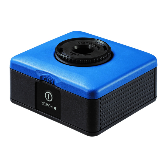
Page 14: Controls And Features
Controls and Features Coupler 1/2-inch microphone adapter NC-74-002 Case top Case bottom Power switch Coupler The microphone of the sound level meter to be calibrated is inserted here. Case top Separate from the case bottom by simultaneously pressing the two sections marked... - Page 15 Two IEC LR6 (size AA) alkaline batteries are inserted here. Lights up when the power switch is set to ON. Power switch Serves to turn the unit on and off. 1/2-inch microphone adapter NC-74-002 Use this adapter when the outer diameter of the microphone is 1/2 inch.
-
Page 16: Preparations
Preparations Inserting the Batteries PUSH 1. Open the case by pressing the sections marked PUSH and pull- ing the case top off the case bottom. Press the PUSH sections on both sides and open the case. 2. Insert two IEC LR6 (size AA) alkaline batteries with correct polarity. - Page 17 Preparations Note - Before inserting the batteries, check the correct + and - orientation as shown on the preceding page. The polarity is also marked inside the battery wells. - Do not mix old and new batteries. - Do not mix different types of batteries. - Always remove the batteries when not using the unit.
-
Page 18: Using The 1/2-Inch Microphone Adapter Nc-74-002
If the outer diameter of the microphone is 1 inch, remove 1/2-inch microphone adapter NC-74-002 the 1/2-inch microphone adapter NC-74-002. When the microphone diameter is 1/2 inches, the adapter must be in place. Important Insert the 1/2-inch microphone adapter NC-74-002 fully into the coupler. Otherwise correct calibration is not possible. -
Page 19: Measurement
ON OFF PUSH 1. Make sure that the power switch of the NC-74 is OFF. 2. Carefully insert the microphone of the sound level meter all the way into the coupler of the sound calibrator. - Page 20 Measurement 3. After inserting the microphone, wait at least 30 seconds before reading the level indication on the sound level meter. Make a note of the reading, because this will be used in step 6. Note Immediately after inserting the microphone, the change in air pressure inside the sound calibrator will lead to false readings, thereby preventing correct calibration.
- Page 21 Measurement 5. Set the power switch of the NC-74 to ON. If the battery voltage of the NC-74 is normal, Power switch the LED lights up. If the voltage is too low, the LED fl ashes. In such a case, replace both batteries with fresh ones.
- Page 22 8. When level adjustment is completed, set the power switch of the sound level meter and the NC-74 to OFF. 9. Carefully remove the microphone of the sound level meter from the NC-74 (see the “Important” on page 7).
-
Page 23: Reference
For the sound level meter NL-21, the calibration value as shown in EXT Cal Table 1 is 93.9 dB. Set the NC-74 to the microphone and adjust the NL-21 so that it reads 93.9 dB. (See the illustration at right.) - Page 24 Reference Calibration Values for Sound Level Meters Class 1 Sound level meter Class 2 Sound level meter Model Microphone Calibration value (dB) Microphone Calibration value (dB) Model NA-16 UC-53A 94.0 NA-20 UC-25 93.5 NA-16A MS-10 93.9 NA-24 UC-52 93.9 NA-25 UC-53A NA-29 94.0...
- Page 25 Reference Calibration Values for Microphones Calibration Nominal outer Model diameter value (dB) UC-11 93.8 UC-27 93.8 1 inch UC-25 93.5 UC-34 93.8 UC-26 93.9 UC-30 94.0 UC-31 93.9 1/2 inch 93.9 UC-52 94.0 UC-53A 94.1 UC-57 94.0 UC-59 MS-10 93.9 Table 2...
- Page 26 Reference Depending on the microphone model, there will be a slight difference in sound pressure level inside the coupler. This is due to differences in the microphone front cavity volume and diaphragm equivalent volume, which cause a difference in the total volume of the coupler.
- Page 27 (without protective grid) 94.25 TOKYO RIKO MR-103 (without protective grid) 94.26 * Using 1/2-inch mi- 1/2-inch microphones crophone adapter UC-26 (with protective grid) 93.91 NC-74-002 UC-30 (with protective grid) 93.98 UC-31 (with protective grid) 94.04 UC-33P (with protective grid) 94.03 RION...
-
Page 28: Electromagnetic Compatibility
Reference Electromagnetic Compatibility Reference orientation for testing effects of exposure to radiofrequency fi elds: Opposite side of microphone insertion opening (see illustration below) Reference orientation for testing effects of exposure to radiofrequency fields... - Page 29 Reference Radiofrequency emissions Electromagnetic fi eld strength of radiofrequency emissions produced by the unit (quasi- peak value at a distance of 10 m) Frequency range 30 MHz to 230 MHz: 30 dB (reference 1 µV/m) or less Frequency range 230 MHz to 1 GHz: 37 dB (reference 1 µV/m) or less The confi guration for greatest radiofrequency emissions: power ON...
- Page 30 Reference Immunity to power-frequency magnetic fi elds and radiofrequency electromagnetic fi elds Sound pressure level deviation when placed under the infl uence of power-frequency mag- netic fi elds and radiofrequency electromagnetic fi elds as specifi ed below: within ±0.3 dB - Electromagnetic fi eld strength up to 10 V/m rms (non-modulated), frequency range 26 MHz to 1 GHz, 900 Hz sinusoidal wave, 80% amplitude modulation - AC magnetic fi eld strength up to 80 A/m rms, frequency 50 Hz and 60 Hz...
-
Page 31: Specifi Cations
1-inch microphones IEC 61094-1 Type LS1P UC-27, UC-11, UC-25, UC-34 1/2-inch microphones IEC 61094-1 Type LS2aP UC-53A, UC-52, UC-26, UC-30, UC-31, UC-33P, UC-57, UC-59 (Using 1/2-inch microphone adapter NC-74-002) Reference conditions Ambient temperature 23ºC Static pressure 101.325 kPa Relative humidity 50%... - Page 32 Specifi cations Nominal sound pressure level 94 dB Specifi ed sound pressure level 94.0 dB (at reference conditions) Sound pressure level tolerance ±0.3 dB Sound pressure level stabilization duration After power-on: 5 seconds or less After microphone insertion: 30 seconds or less Sound pressure level stability (short-term fl uctuations) ±0.1 dB (within ambient conditions for operation) [20 s, Time Weighting F (IEC 61672-1:2002)]...
- Page 33 Frequency (deviation from value for reference conditions) within ±1.0% Ambient ratings Ambient temperature: -10 to +50ºC Static pressure: 65 to 108 kPa Relative humidity: 25 to 90% RH 1/2-inch microphone adapter (supplied accessory) Model designation NC-74-002 Load volume 767 mm (typical value)
- Page 34 Specifi cations Sound pressure level variation caused by effective microphone load volume variation -0.00072 dB/mm (typical value) Power supply Two IEC LR6 (size AA) alkaline batteries Power supply voltage Nominal 3.0 V, Maximum 3.3 V, Minimum 2.3 V Specifi ed sound pressure level deviation within power supply voltage range Max.
- Page 35 200 g (including batteries) Atmospheric pressure compensation The NC-74 automatically compensates for sound pressure fl uctuations caused by changes in static pressure. Sound pressure level devia- tion between 65 and 108 kPa is within ±0.3 dB from the value for 101.325 kPa.
- Page 36 Specifi cations 1/2-inch microphone adapter NC-74-002 Unit: mm Dimensional Drawings...
- Page 38 No. 32263 14-08...
Need help?
Do you have a question about the NC-74 and is the answer not in the manual?
Questions and answers