
Related Manuals for Rion VE-10


Summary of Contents for Rion VE-10
- Page 1 INSTRUCTION MANUAL CALIBRATION EXCITER VE-10 3-20-41 Higashimotomachi, Kokubunji, Tokyo 185-8533, Japan http://www.rion.co.jp/english/...
- Page 3 Organization of This Manual This manual describes the features and operation principles of the Vibration Exciter VE-10. To ensure safety and accuracy, please read this document carefully. The manual contains the following sections. Outline Gives basic information on the unit.
- Page 4 To conform to the EU requirement of the Directive on Waste Elec- trical and Electronic Equipment, the symbol mark on the right is shown on the instrument. T h e pro d u c t d e s c r i b e d in t hi s m anu al i s in c o nfor m it y wit h t he fo llowing Euro pean st and ar d s;...
- Page 5 Operating Precautions - Operate the unit only as described in this manual. - Do not disassemble or modify the unit. - In the vicinity of a strong magnetic fi eld (such as produced by magnets, motors, speakers, etc.), measurement results may be affected. - The calibration exciter in the unit uses a semipermanent magnet.
-
Page 7: Table Of Contents
Contents Operating Precautions ..................iii Outline ......................1 Parts and Functions ...................2 Preparations ......................3 Loading Battery ...................3 Attaching Vibration Pickup .................4 Operation Mode ...................9 Calibration ...................... 10 Calibration of Vibration Measurement System ........... 10 Sensitivity Check of Accelerometer ............11 Specifi cations ....................12... -
Page 9: Outline
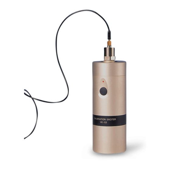
Outline The VE-10 is a portable vibration exciter designed for calibration of vibration pickup, vibra- tion meter, vibration measurement system, etc. The VE-10 generates a sinusoidal vibration of 10 m/s (rms) in acceleration, 10 mm/s (rms) in velocity, 10 μm (rms) in displacement. -
Page 10: Parts And Functions
Parts and Functions Exciter Vibration pickup or adapter is mounted here. Power indicator Lights up when the power is switched on. Power/mode switch Serves to on/off the power and switches the operation mode. Bottom case Battery compartment is located inside this case. -
Page 11: Preparations
Preparations Loading Battery Battery connector Battery 1. Turn the bottom case counterclockwise and take it off. 2. With the correct polarity, attach a 6LR61 alkaline battery to the battery connector. 3. Insert the battery in the battery compart- ment. 4. Screw the bottom case on the unit. Note If continuous mode cannot be activated, or if Do not try to turn or... -
Page 12: Attaching Vibration Pickup
Preparations Attaching Vibration Pickup Attach the vibration pickup to the VE-10 with one Vibration Pickup of the following methods, and connect the pickup to the input connector of vibration meter using a low-noise cable. Low-noise cable Torque for fastening the vibration pickup and adapter will be 0.1 N . - Page 13 Preparations Vibration Pickup with M6 screw hole Mount the vibration pickup on the exciter with the M6 screw. Vibration Pickup Vibration Pickup with UNF screw hole 1. Attach the M6-UNF screw (UNF side) to the vibration pickup. 2. Mount the vibration pickup on the exciter using M6 screw the M6 side of M6-UNF screw.
- Page 14 Preparations Vibration Pickup with M6 screw hole (using magnet attachment) 1. Mount the vibration pickup on the magnet Vibration Pickup attachment with the M6 screw. 2. Mount the adapter on the exciter. 3. Attach the magnet to the adapter. M6 screw Note M6-UNF screw To remove the magnet, slide it on the adapter.
- Page 15 Preparations Vibration Pickup with UNF screw hole (using magnet attachment) 1. Attach the M6-UNF screw (UNF side) to the vibration pickup. 2. Mount the vibration pickup on the magnet attachment using the M6 side of M6-UNF screw. 3. Mount the adapter on the exciter. 4.
- Page 16 Preparations Adhesive mounting type vibration pickup Vibration Pickup 1. Mount the adapter on the exciter. 2. Attach the vibration pickup to the adapter with Adhesive tape both-sided adhesive tape. Note Adapter When attaching a triaxial type vibration pickup, be careful of the measurement axes (X, Y, Z). Exciter...
-
Page 17: Operation Mode
Preparations Operation Mode The VE-10 provides two operation modes. The mode can be changed by pressing the power/mode switch. Note Do not press the switch strongly with a sharp pointed object such as pointed tweezers. Auto-stop pushes once Power/mode switch... -
Page 18: Calibration
Calibration The VE-10 should be in the soft case when performing calibration. Also, do not give vibra- tions to the VE-10 especially when calibrating in velocity and displacement. Calibration of Vibration Measurement System 1. Set the sensitivity of the vibration meter to the sensitivity of the vibration pickup in use. -
Page 19: Sensitivity Check Of Accelerometer
Calibration Sensitivity Check of Accelerometer 1. Set the sensitivity of the meter to the sensitivity of the accelerometer. 2. Set the measurement range of the vibration meter to measure 10 m/s (rms) for ac- celeration. 3. Press once the power/mode switch. The power indicator lights up. 4. -
Page 20: Specifi Cations
Specifi cations Frequency: 159.2 Hz ± 1 % (-10ºC to +55ºC) Acceleration: 10 m/s (rms) 14.14 m/s (peak) ±3% (+10ºC to +40ºC) ±5% (-10ºC to +55ºC) Velocity: 10 mm/s (rms) 14.14 mm/s (peak) ±4% (+10ºC to +40ºC) ±6% (-10ºC to +55ºC) Displacement: 10 μm (rms) 14.14 μm (peak) - Page 21 Specifi cations Transverse amplitude: 5% or less of main axis amplitude Maximum load: 70 g Total harmonic distortion: 3% or less (20 g to 60 g load) 5% or less (10 g to 70 g load) Overload detection: Automatically stops operation for more than 100 g load Operation mode: Auto-stop (approx.
- Page 22 Specifi cations Supplied accessories: Adapter M6 screw M6-UNF screw Soft case 6LR61 alkaline battery Instruction manual Inspection certifi cate...
- Page 23 Specifi cations Unit: mm Dimensional drawing of VE-10...
- Page 24 No. 00819 16-03...
Need help?
Do you have a question about the VE-10 and is the answer not in the manual?
Questions and answers