
Related Manuals for Aircraft in Miniature Limited TRANSPORT WINGS DC-10-30 KIT


Summary of Contents for Aircraft in Miniature Limited TRANSPORT WINGS DC-10-30 KIT
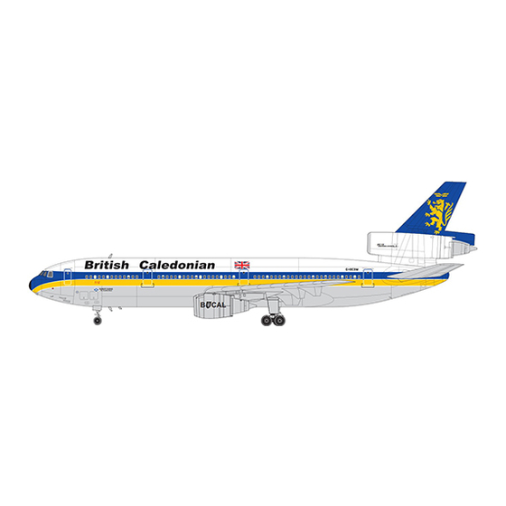
- Page 1 TRANSPORT WINGS 1:72 Mixed-media kit of the DC-10-30 Second generation jet airliner History, Notes and Instructions...
- Page 2 Introduction TRANSPORT WINGS kits are model kits of large aircraft. They are suitable for the experienced modeller, who can now own 1:72 models of many of the world's largest airliners and their military transport variants. Because of their size, they are moulded in very heavy (2 mm) plastic, and are supplied with all parts pre-cut.
- Page 3 PARTS LIST Vacformed Part Resin Parts Fuselage-keel....1 off Air conditioning inlets/outlets. . . 1 sprue of 7 Fuselage-left ....1 off Centre engine bypass duct - left ..1 off Fuselage-right .
- Page 4 Etched brass detail parts (Spare items shown in red) Scribing template...
-
Page 5: Fuselage Assembly
GENERAL WARNINGS 1 - THIS KIT CONTAINS SMALL AND/OR SHARP PARTS. KEEP THE CONTENTS OF THE KIT AWAY FROM CHILDREN. 2 - THIS KIT CAN CONTAIN PRECUT PARTS WITH SHARP EDGES OR CORNERS. BE CAREFUL WHEN YOU HANDLE THESE PARTS BECAUSE THEY CAN CAUSE CUTS OR OTHER INJURIES. - Page 6 Aircraft LANDING GEAR DOOR DIMENSIONS These doors are closed when gear is down Position of nose NOSE LANDING landing gear leg GEAR DOORS Door hangs down from this edge, parallel to main landing gear leg 9 mm These doors are open Note: Doors are symetrical when gear is down about aircraft centreline...
- Page 7 (4) Make the NLG and CLG bay parts. (a) For the NLG cut out these parts from the .080"/2 mm plastic sheet supplied: Roof panel - 50 mm x 22 mm Two side panels, each 50 mm x 20 mm Front and rear bulkheads to the shape shown below.
- Page 8 (8) Assemble the NLG and CLG bays. (a) Drill holes in the side panels for the pins on the landing gear legs and nose gear drag link. (b) Assemble each of the two landing gear bays. Drill holes in the side panels for the pins on the landing gear legs and nose gear drag link.
- Page 9 (10) NACA intakes and exhaust outlets. (a) Decide is the exhaust outlet doors are to be open or closed. If they are to be open, cut out the areas for the intakes and the outlets. If they are to be closed, use the scribing template and scribe the outlines of the doors.
- Page 10 (12) Fuselage assembly. (a) Attach these sub-assemblies to one fuselage half: - NLG bay - CLG bay - Centre engine intake duct - Centre engine assembly - Keel (put the keel into the fuselage to half its depth and flood the joint with liquid cement). (b) When the keel is securely bonded to the fuselage half, file the mating face of the keel to suit the curvature of the other fuselage half.
- Page 11 Cut out the main landing gear doors in the wing lower surface. Make two sets of main landing gear bay parts. Cut out these parts from the .080"/2 mm plastic sheet supplied: Packers to let the T-brackets sit horizontally Panels to fill the space between the upper and lower faces of the wing, to give the fore and aft faces of the main landing gear bay structure.
-
Page 12: Final Assembly
FINAL ASSEMBLY Attach the wings to the fuselage. Put the wing attachment block into the cutout in the fuselage. and attach the wings. Ft the engine sub-assemblies into the sockets in the under side of the wing and cement them in place. Cement the main landing gear legs and side braces in place with super glue or epoxy adhesive. - Page 13 Fit the centre main landing gear components as shown below. Fit the nose landing gear components as shown below. G. Attach the flap tracks, intake fences and other detail parts in position with super glue. We recommend that you refer to photographs of an actual aircraft if posible.
- Page 14 1A 1D STENCIL DECALS ON WING ENGINES STENCIL DECALS ON WING ENGINES (RIGHT SIDE) (LEFT SIDE) 4J 4J STENCIL DECALS ON CENTRE (TAIL) ENGINE STENCIL DECALS ON CENTRE (TAIL) ENGINE (RIGHT SIDE) (LEFT SIDE) STENCIL DECALS ON DOOR STENCIL DECALS ON CARGO DOOR LEFT REAR LOWER FUSELAGE RIGHT REAR LOWER FUSELAGE...
- Page 15 EMERGENCY OPENING EMERGENCY OPENING 1 PULL OPERATING HANDLE OUT 1 PULL OPERATING HANDLE OUT OF FUSELAGE NOTE 1: REMOVE THESE PANELS OF FUSELAGE 2 ROTATE EMERGENCY OVER 2 ROTATE EMERGENCY OVER RIDE LEVER FROM SAFE RIDE LEVER FROM SAFE POSITION TO EMERGENCY FOR B CAL AIRCRAFT.
- Page 16 TYPICAL 15 POSITIONS NO STEP AFT ON EACH UPPER WING HOIST TYPICAL 9 POSITIONS ON EACH UPPER WING STENCIL DECALS ON RIGHT UPPER WING (LEFT WING SIMILAR)
- Page 17 HOIST PLACARD HOIST TYPICAL 10 PLACES STENCIL DECALS ON LOWER FACE OF THE RIGHT HORIZONTAL STABILIZER AND ELEVATOR (LEFT SIDE SIMILAR) CENTRELINE GEAR RIGHT MAIN DOOR MAX. TOW ANGLE DO NOT EXCEED MAX. TOW ANGLE MAX. TOW ANGLE DO NOT EXCEED DO NOT EXCEED CAUTION DO NOT UN-LOCK LANDING GEAR...
- Page 20 NOTES IF THESE INSTRUCTIONS ARE UPDATED, THEY CAN BE DOWNLOADED FROM OUR WEBSITE - www.aim72.co.uk © Aircraft In Miniature Ltd 2010 - initial issue - 26 February 2010 The manufacturers reserve the right to alter parts; add to, or delete parts without prior notification in the interests of quality control, production, or product improvement.
Need help?
Do you have a question about the TRANSPORT WINGS DC-10-30 KIT and is the answer not in the manual?
Questions and answers