
Related Manuals for Aircraft in Miniature Limited Historic Wings Wright Flyer 1 1903


Summary of Contents for Aircraft in Miniature Limited Historic Wings Wright Flyer 1 1903
- Page 1 Historic Wings 1:72 Metal Kit of the © Copyright unknown 1903 Wright Flyer 1 History, Notes and Assembly Instructions...
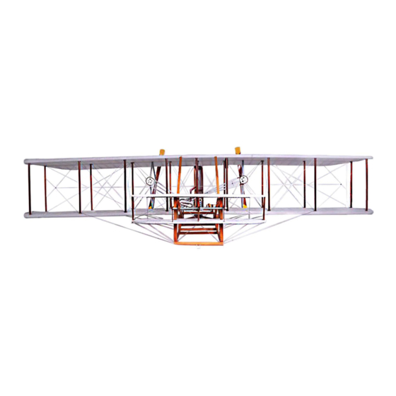
- Page 2 History On December 17, 1903, the Wright brothers made the first successful controlled flight of a heavier-than-air flying machine at Kitty Hawk, North Carolina. This aircraft, known as the Wright Flyer, was the result of a four-year long program of research and development conducted by Wilbur and Orville Wright beginning in 1899. The Wright brothers had a passing interest in flight as youngsters.
-
Page 3: Parts List
Introduction This Historic Wings kit is made from etched brass for the main structure, with cast metal detail parts. The flying surfaces can be covered with the tissue paper supplied, although many modellers may prefer to leave the structure uncovered to show the details. Brass components can be soldered together, or joined with cyanoacrylate (SuperGlue) or 5-minute epoxy. - Page 4 Fret 2 5 off R2 - 6 off P4 - x2 F6 - x2 Wright Flier 1 - Part No. HW03-006/01 - ©Aircraft In Miniature Ltd 2003 C2 ..Foot cradle body E3 ..Elevator strut (x5) F7 .
- Page 5 Assemble the rudders (Refer to Figure 4 ) A Fold the rudder structure (Refer to Figure 4, Detail A) NOTE - The fold lines are on the lower face before the item is folded, so they are inside the structure after it is folded. Attach the six rudder struts (R2), and the rudder mounting (R3).
- Page 6 Cover each of the f lying surfaces with tissue paper (if required - Refer to Figure 5). A Cover a flying surface NOTES:1 - An elevator is illustrated, but the same procedure is used for all the flying surfaces. 2 - The flying surfaces are the two wings, the two elevators and the rudder. (1) Paint the structure.
- Page 7 Assemble the wings, elevators and rudders to the fuselage (Refer to Figure 7) . A Attach the wings to the fuselage frames. (1) Attach the rib doubler of the left fuselage frame (F1) to the inboard face of the outboard pilot support rib of the lower wing.
- Page 8 The manufacturers reserve the right to alter parts; add to, or delete parts without prior notification in the interests of quality control, production, or product improvement. This kit is manufactured in the United Kingdom by Aircraft In Miniature Limited 19, Watling Street, Nuneaton, Warwickshire, CV11 6JJ, England Email: info@aim72.co.uk - Web site: www.aim72.co.uk...
Need help?
Do you have a question about the Historic Wings Wright Flyer 1 1903 and is the answer not in the manual?
Questions and answers