Advertisement
Quick Links
Advertisement

Related Manuals for BLB hydraulic BM40 Series

Summary of Contents for BLB hydraulic BM40 Series
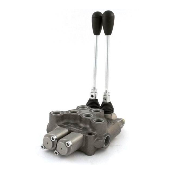
- Page 1 BM40 MONOBLOCK DIRECTIONAL CONTROL VALVES INSTRUCTIONS MANUAL UPGRADE YOUR HYDRAULIC CONTROL...
- Page 2 86503000 - 91411009 ITEM BM40/1 ZB GU P/MO B1/T TAR5 BM40/1 installation dimensions BM40 MONOBLOCK DIRECTIONAL CONTROL VALVES INSTRUCTIONS MANUAL...
- Page 3 86503001 – 91411019 ITEM BM40/1 ZB GU P/MO A1/T TAR5 BM40/1 installation dimensions BM40 MONOBLOCK DIRECTIONAL CONTROL VALVES INSTRUCTIONS MANUAL...
- Page 4 86503002 – 91411010 ITEM BM40/2 ZB GU P/MO B1/MO B1/T TAR5 BM40/2 installation dimensions BM40 MONOBLOCK DIRECTIONAL CONTROL VALVES INSTRUCTIONS MANUAL...
- Page 5 86503003 – 91411020 ITEM BM40/2 ZB GU P/MO A1/MO A1/T TAR5 BM40/2 installation dimensions BM40 MONOBLOCK DIRECTIONAL CONTROL VALVES INSTRUCTIONS MANUAL...
- Page 6 86503004 – 91411021 ITEM BM40/3 ZB GU P/MO A1/MO A1/MO A1/T TAR5 BM40/3 installation dimensions BM40 MONOBLOCK DIRECTIONAL CONTROL VALVES INSTRUCTIONS MANUAL...
- Page 7 86503005 – 92111005 ITEM BM40/4 ZB GU P/MO A1/MO A1/MO A1/MO A1/T TAR5 BM40/4 installation dimensions BM40 MONOBLOCK DIRECTIONAL CONTROL VALVES INSTRUCTIONS MANUAL...
- Page 8 86503006 – 92111006 ITEM BM40/5 ZB GU P/MO A1/MO A1/MO A1/MO A1/MO A1/T TAR5 BM40/5 installation dimensions BM40 MONOBLOCK DIRECTIONAL CONTROL VALVES INSTRUCTIONS MANUAL...
- Page 9 86503007 – 92111001 ITEM BM40/6 ZB GU P/MO A1/MO A1/MO A1/MO A1/MO A1/MO A1/T TAR5 BM40/6 installation dimensions BM40 MONOBLOCK DIRECTIONAL CONTROL VALVES INSTRUCTIONS MANUAL...
- Page 10 86503008 – 91411011 ITEM BM40/7 ZB GU P/MO A1/MO A1/MO A1/MO A1/MO A1/MO A1/MO A1/T TAR5 BM40/7 installation dimensions BM40 MONOBLOCK DIRECTIONAL CONTROL VALVES INSTRUCTIONS MANUAL...
-
Page 11: Technical Specifications
TECHNICAL SPECIFICATIONS MAIN FEATURES Work Flow / Max Flow 35 l/min / 45 l/min Zinc plating protects against corrosion and rust Relief valve setting 140 bar Precise flow metering to accurately control actuator speed Relief valve range 100 to 250 bar Power beyond capability for easy addition of valves downstream Inlet/Outlet Ports 1/2"... -
Page 12: Parts List
PARTS LIST: Drawing 1 BM40 SPARE PARTS Nº PARTS PARTS Nº SUB PART SUB PART Adjusting Screw Relief Valve Kit Check Valve Handle Handle Cap Handle Cap Kit Screw O-Ring Seal Spool Kit Spool Spool Control Cap Spool Control kit Positioner Kit Screw INSTALLATION... - Page 13 COMPONENT THREAD Fixing Screws Before installing the product, check that it has not been 3/8” G; 3/4”-16 UNF damaged during internal transport. Connectors, Plugs 1/2” G; 7/8”-14 UNF Relief Valve, RVP M20 x 1,5 Step 1. Install the valve in shock and vibration free areas. While moving the valve do not cause accidental bumps or shocks. The valve must be secured with M8 screws.
- Page 14 OPTIONAL Carry Over - CO (Power Beyond Adapter) Closed Center Plug - CCP Relief Valve Plug - RVP BM40 MONOBLOCK DIRECTIONAL CONTROL VALVES INSTRUCTIONS MANUAL...
- Page 15 HOW TO INSTALL CARRY OVER - CO (POWER BEYOND ADAPTER) Step 1. Screw the Power Beyond Adapter into the T2 port with 27 mm hex wrench and tighten to 45 Nm. When the Power Beyond Adapter is installed a hose must be attached to the T port and run back to the tank. Failure to do this will cause the valve not to function properly.
- Page 16 BLB S.r.l. Via Natta, 1 36040 Brendola (VI) - Italy T. +39 0444 401141 Quality management system certified according to ISO 9001: W. www.blbhydraulic.com 2008 Certicate Nr 50 100 11533...
Need help?
Do you have a question about the BM40 Series and is the answer not in the manual?
Questions and answers