Table of Contents
Advertisement
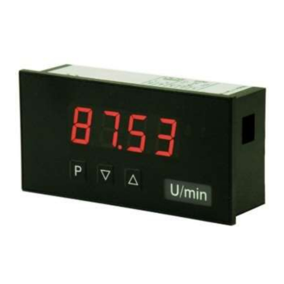
User Manual M1
Direct current / Direct voltage signals 0-20 mA, 4-20 mA, 0-10 VDC
Installation size 96x48 mm (BxH)
Installation size mm (BxH)
Technical features:
• red display of -1999...9999 digits (optional: green, orange or blue)
• minimal installation depth: 25 mm, 27 mm, 60 mm or 71 mm without plug-in terminal
• adjustment via factory default or directly on the sensor signal
• min/max-memory
• 10 adjustable supporting points
• display flashing at threshold exceedance / undershooting
• tara function
• programming interlock via access code
• protection class IP65 at the front
• plug-in terminal
• pc-based configuration software PM-TOOL with CD and USB-adapter
• on request: devices for operating temperature of -40°...+70°C (M1O)
M1_x1GB.pdf update: 04.11.2020
Installation size 48x24 mm (BxH)
Installation size 72x36 mm (BxH)
Advertisement
Table of Contents

Related Manuals for montwill M1


Summary of Contents for montwill M1
- Page 1 User Manual M1 Direct current / Direct voltage signals 0-20 mA, 4-20 mA, 0-10 VDC Installation size 48x24 mm (BxH) Installation size 96x48 mm (BxH) Installation size mm (BxH) Installation size 72x36 mm (BxH) Technical features: • red display of -1999…9999 digits (optional: green, orange or blue) •...
- Page 2 96x48x25 mm 96x24x57 mm Switching points 72x36x71 mm 0 no switching point 48x24x27 mm 2 relay outputs (only M1-6 devices) Display type Protection class Current, voltage 1 without keypad, operation via PM-TOOL 7 IP65 / plug-in terminal Display colour...
-
Page 3: Table Of Contents
Content 1. Brief description 2. Assembly 3. Electrical connection and connection examples 4. Function description and operation 4.1. Programming software PM-TOOL 5. Setting up the device 5.1. Switching on 5.2. Standard parameterisation (flat operation level) Value assignment for control of the signal input 5.3. -
Page 4: Brief Description
1. Brief description / 2. Assembly 1. Brief description The panel instrument M1-x1 is a 4-digit device for direct voltage and direct current signals and a visual limit value monitoring via the display. The configuration happens via three front keys or via the optional PC-software PM-TOOL. An integrated programming lock prevents unrequested changes of the parameter and can be unlocked again via an individual code. -
Page 5: Electrical Connection And Connection Examples
Type M1-3VR4B.0001.770xD (96x24 mm) Type M1-7VR4A.0001.770xD (48x24 mm) 230 VAC 24 VDC _ < _ < 3 VA 1 VA 0/4...20 mA 0/4...20 mA 0...10 V 0...10 V Type M1-6VR4B.0001.570CD / M1-6VR4B.0001.770xD (Housing 72x36 mm) Option: 230 VAC 24 VDC Signal input... - Page 6 3. Electrical connection Connection examples: Below you find some connection examples, which demonstrate some practical applications: M1-1/3/7 in combination with M1-1/3/7 in combination with M1-1/3/7 in combination with a 2-wire-sensor 4-20 mA a 3-wire-sensor 0/4-20 mA a 3-wire-sensor 0-10 V...
-
Page 7: Function Description And Operation
4. Function description and operation 4. Function description and operation Operation The operation is divided into two different levels. Menu Level Here it is possible to navigate between the individual menu items. Parameterization level: The parameters stored in the menu item can be parameterized here. Functions that can be adjusted or changed are always indicated with a flashing of the display. -
Page 8: Setting Up The Device
5. Setting up the device 5. Setting up the device 5.1. Switching on Once the installation is complete, you can start the device by applying the current loop. Check beforehand once again that all the electrical connections are correct. Starting sequence For 1 second during the switching-on process, the segment test ( ) is displayed, followed by an indication of the software type and, after that, also for 1 second, the software... -
Page 9: Programming Interlock
5. Setting up the device Menu level Parameterization level Setting the decimal point, Default: The decimal point on the display can be moved with [▲] [▼] and confirmed with [P]. The display then switches back to the menu level again. Setting the display time, Default: dann... -
Page 10: Extended Parameterisation
5. Setting up the device 5.4. Extended parameterization By pressing the [▲] & [▼] keys during standard parameterization for one second, the display switches to the extended parameterization mode. Operation is the same as in standard parameterization. Menu level Parameterization level Rescaling the measuring input values, With the aid of this function, one can rescale the input value of e.g. -
Page 11: Allocation Of Functions Onto The Navigation Keys
5. Setting up the device Menu level Parameterization level Min/max-value inquiry - assignment of key functions, Default: For the operating mode enter here either a min/max-value inquiry or a threshold value correction on the arrow keys. If the min/max-memory was activated with , the measured min/max-values will be saved during operation and can be called up via the arrow keys [▲] [▼]. - Page 12 5. Setting up the device Menu level Parameterization level Function if display falls below / exceeds limit value, Default: To indicate if the value falls below the lower limit value, can be selected (LOW = lower limit value) and if it goes above the upper limit value, can be selected (HIGH = upper limit value).
-
Page 13: Safety Parameter For Locking Of The Programming
5. Setting up the device Menu level Parameterization level Setting the code, Default: With this setting, it is possible to select an individual code (works setting ) for locking the keyboard. To lock/release the key, proceed according to menu item Supporting points - number of additional supporting points, Default: In addition to the start and end value, 8 extra supporting points can be defined to... -
Page 14: Reset To Default Values
6. Reset to default values 6. Reset to default values To return the unit to a defined basic state, a reset can be carried out to the default values. The following procedure should be used: • Switch off the power supply •... -
Page 15: Alarms / Switching Points
7. Functional principle of the switching points 7. Functional principle of the switching points Limit value exceedance “ ” The switching point S1-S2 is “off” below the threshold and “on” on reaching the threshold. Schaltpunkt Schaltschwelle Anzeige Hysterese Limit value undercut “... -
Page 16: Technical Data
8. Technical data 8. Technical data Housing Dimensions 96x48x25 mm (BxHxD), D = 38 mm including plug-in terminal 96x24x60 mm (BxHxD), D = 74 mm including plug-in terminal 72x36x71 mm (BxHxD), D = 100 mm including plug-in terminal 48x24x27 mm (BxHxD), D = 54 mm including plug-in terminal Panel cut-out 92.0 +0.8... - Page 17 8. Technical data Switching outputs Type Switching contact 250 VAC / 5 AAC; 30 VDC / 5 ADC Only in housing size Relay with change-over 30 x 10 bei 5 AAC, 5 ADC at ohm resistive 72x36 mm contact burden 10 x 10 mechanically Separation according to DIN EN50178 /...
-
Page 18: Safety Advices
Please inform the supplier immediately of any damage. Installation The M1-x1-device must be installed by a suitably qualified specialist (e.g. with a qualification in industrial electronics). Notes on installation •... -
Page 19: Error Elimination
10. Error elimination 10. Error elimination Error description Measures The unit permanently indicates • The input has a very high measurement, check overflow. the measuring circuit. • With a selected input with a low voltage signal, it is only connected on one side or the input is open. - Page 20 M1_x1GB.pdf Update: 04.11.2020...
Need help?
Do you have a question about the M1 and is the answer not in the manual?
Questions and answers