Table of Contents
Advertisement
Quick Links
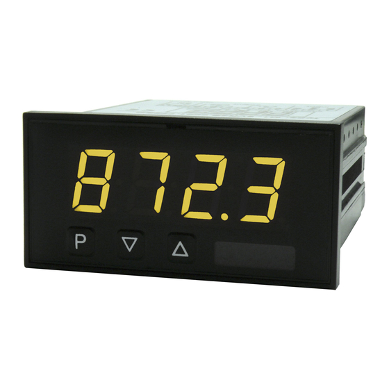
User Manual M1
Pt1000 2-wire -200...850°C / -328...1562°F
Technical features:
• red display of -1999...9999 digits (optional: green, orange or blue display)
• minimal installation depth: 25 mm without plug-in terminal
• adjustment via factory default or directly on the sensor signal
• min/max-memory
• displayed in °C/°F
• display flashing at threshold exceedance / undershooting
• impedance matching
• programming interlock via access code
• protection class IP65 at the front
• plug-in terminal
• pc-based configuration software PM-TOOL with CD and USB-adapter for
devices without keypad for a simple adjustment of standard devices
M1_1C6GB.pdf update: 27.05.2020
96x48
Advertisement
Table of Contents

Related Manuals for montwill M1


Summary of Contents for montwill M1
- Page 1 User Manual M1 Pt1000 2-wire -200…850°C / -328…1562°F Technical features: • red display of -1999…9999 digits (optional: green, orange or blue display) • minimal installation depth: 25 mm without plug-in terminal • adjustment via factory default or directly on the sensor signal •...
- Page 2 Identification STANDARD TYPES ORDER NUMBER Pt1000 2-wire M1-1TR4B.030C.570xD Housing size: 96x48 mm M1-1TR4B.030C.770xD Options – breakdown of order code: M 1- 1 T R 4 B. 0 6 0 C. 7 7 0 x D Basic type M-Line Dimension D physical Unit...
-
Page 3: Table Of Contents
Content 1. Brief description 2. Assembly 3. Electrical connection and connection examples 4. Function description and operation 4.1. Programming software PM-TOOL 5. Setting up the device 5.1. Switching on 5.2. Standard parameterisation (flat operation level) Value assignment for control of the signal input, displayed in °C/°F, impedance matching 5.3. -
Page 4: Brief Description
1. Brief description / 2. Assembly 1. Brief description The panel instrument M1-1C6 is a 4-digit device for temperature metering via Pt1000- sensors and a visual limit value monitoring via the display. The configuration happens via three front keys or via the optional PC-software PM-TOOL. An integrated programming interlock prevents unrequested changes of the parameter and can be unlocked again via an individual code. -
Page 5: Electrical Connection And Connection Examples
3. Electrical connection Type M1-1VR4B.0001.570xD with a supply of 230 VAC Pt1000 2-wire 230 VAC < _ 3 VA Type M1-1VR4B.0001.770xD with a supply of 24 VDC, galv. isolated Pt1000 2-wire 24 VDC < _ 1 VA Advice: The galvanic isolation in devices with temperature sensors, that do not have a galvanic connection to an extrinsic potential, can be cancelled by an bridge from terminal 3 to 4 and thus stabilise the device against external failures. -
Page 6: Function Description And Operation
4. Function description and operation 4. Function description and operation Operation The operation is divided into two different levels. Menu Level Here it is possible to navigate between the individual menu items. Parameterization level: The parameters stored in the menu item can be parameterized here. Functions that can be adjusted or changed, are always indicated with a flashing of the display. -
Page 7: Setting Up The Device
5. Setting up the device 5. Setting up the device 5.1. Switching on Once the installation is complete, start the device by applying the current loop. Check beforehand once again that all the electrical connections are correct. Starting sequence For 1 second during the switching-on process, the segment test ( ) is displayed, followed by an indication of the software type and, after that, also for 1 second, the software version. -
Page 8: Programming Interlock
5. Setting up the device Menu level Parameterization level Setting the display time, Default: then The display time is set with [▲] [▼]. The display moves up in increments of 0.1 sec up to 1 second and in increments of 1.0 to 10.0 seconds. Confirm the selection by pressing the [P] button. -
Page 9: Extended Parameterisation
5. Setting up the device 5.4. Extended parameterization By pressing the [▲] & [▼] keys during standard parameterization for one second, the display switches to the extended parameterization mode. Operation is the same as in standard parameterization. Menu level Parameterization level Min/max-value inquiry - assignment of key functions, Default: Here, you can enter for the operating mode either a min/max-value inquiry or a... -
Page 10: Safety Parameter For Locking Of The Programming
5. Setting up the device Menu level Parameterization level Function if display falls below / exceeds limit value, Default: To indicate if the value falls below the lower limit value, can be selected (LOW = lower limit value) and if it goes above the upper limit value, can be selected (HIGH = upper limit value). -
Page 11: Reset To Default Values
6. Reset to default values 6. Reset to default values To return the unit to a defined basic state, a reset can be carried out to the default values. The following procedure should be used: • Switch off the power supply •... -
Page 12: Alarms / Switching Points
7. Functional principle of the switching points 7. Functional principle of the switching points Limit value exceedance “ ” The switching point S1-S2 is “off” below the threshold and “on” on reaching the threshold. Limit value undercut “ ” The switching point S1-S2 is “on” below the threshold and switched “off” on reaching the threshold. -
Page 13: Technical Data
8. Technical data 8. Technical data Housing Dimensions 96x48x25 mm (BxHxD) 96x48x38 mm (BxHxD) including plug-in terminal Panel cut-out 92.0 +0.8 x 45.0 +0.6 Insulation thickness up to 3 mm Fixing snap-in screw element Material PC Polycarbonate, black, UL94V-0 Sealing material EPDM, 65 Shore, black Protection class standard IP65 (front), IP00 (back side) - Page 14 8. Technical data Ambient conditions Working temperature 0°C…60°C Storing temperature -20°C…80°C Weathering resistance relative humidity 0-80% on years average without dew EN 61326 CE-sign Conformity to directive 2014/30/EU Safety standard According to low voltage directive 2014/35/EU EN 61010; EN 60664-1...
-
Page 15: Safety Advices
Please inform the supplier immediately of any damage. Installation The M1-1C6-device must be installed by a suitably qualified specialist (e.g. with a qualification in industrial electronics). Notes on installation •... -
Page 16: Error Elimination
10. Error elimination 10. Error elimination Error description Measures The unit permanently indicates • The input has a very high measurement, overflow. check the measuring circuit. • The input is open. The unit permanently shows • The input has a very low measurement, underflow.
Need help?
Do you have a question about the M1 and is the answer not in the manual?
Questions and answers